background image

9

English

Installation Pr

oc

edur

e

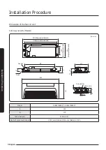
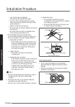
Slim 1 way cassette (Large)

(Unit: mm)

1380 (Ceiling opening diameter)

1200

Drain hole

1410

A

85

Ceiling

B

500

30

85

50

40

35

100

Water outlet side

450

Water inlet side

1260 (Space between the fixing bolts)

350


(Spac

e betw

een 

the 

fixing bolts)

470


(C

eil

ing opening diamet

er)

Model

AG042TN1DKH*

A

138

B

180

Connection port

PF Male (3/4")

Flexible hose connection port

VP25 (outer diameter: Ø 32, inner diameter: Ø 25)

  NOTE

•  The shape of the fan coil unit may differ depending on the model.
•  When installing a cassette type product on a ceiling with a temperature of 27 °C or more and a humidity of 80% or 

more, install polyethylene foam or a similar insulation material with a thickness of 10 mm or more onto the fan coil 
unit body.

•  The recommended ceiling height is 2.7 m.

Summary of Contents for AGTN1DKH Series

Page 1: ...Fan Coil Unit Installation manual AG TN1DKH Thank you for purchasing this Samsung Fan Coil Unit Before operating this unit please read this manual carefully and retain it for future reference ...

Page 2: ...rging inert gas from the fan coil unit 12 Step 6 Connecting the water pipes 13 Step 7 Performing the water leak test and insulating the piping 13 Step 8 Installing the water pipes 15 Step 9 Connecting the drain hose 17 Step10 Connecting the power and communication cables 21 Step11 Optional Extending the power cable 25 Step12 Setting the fan coil unit addresses and installation options 26 Step13 Pe...

Page 3: ...rflow of cold water be sure to install a 2 way electric valve If not installed water overflow and condensation may occur When the fan coil unit is stopped the interworking control with the 2 way electric value valve closed blocks cold waterfrom circulating to prevent condensation inside the product If no 2 way electric valve is installed condensation water may be generated and condensation may dev...

Page 4: ...e electric shock orfire After completing the installation check the following before operating the product The piping is connected correctly and securely and there is no water leakage Do not modify and extend the power cable Avoid complicated wirings Failure to do so may cause connection defect insulation defect or overcurrent leading to electric shock orfire If you need to extend the power cable ...

Page 5: ...ntact a facility specialist Where exposed to combustible gas carbon fiber flammable powder or dust orwhere volatile combustion gases such as thinner or gasoline are used Gases nearthe fan coil unit may ignite Where electromagnetic interferences are generated The control unit may not operate Where the air contains a high level of salinity such as nearthe sea orwhere voltage fluctuates significantly...

Page 6: ...product Do not install the product if it has been scratched during transportation Perform the drainage work as described in this installation manual so that condensation water can be reliably drained and insulate the drain pipe so that no condensation can be generated Incomplete drainage work may cause water leakage leading to property damage Install the power and communication cables of the fan c...

Page 7: ...t structure must be strong enough to support the weight of the fan coil unit If the structure is not strong the fan coil unit may fall off leading to personal injury The ceiling must not be significantly sloped There must be a sufficient space for maintenance and service The power and communication cables of the fan coil unit must be at least1 m away from electronic appliances such as televisions ...

Page 8: ...ningdimension 970 Drainhole 1198 410 Ceiling A 80 B 500 80 35 22 Wateroutletside Waterinletside 50 77 46 1036 Spaceofsuspensionbolts 249 Space of suspension bolts 440 Ceiling opening dimension Model AG026TN1DKH AG032TN1DKH A 135 B 175 Connection port PF Male 3 4 Flexible hose connection port VP20 outerdiameter Ø 26 innerdiameter Ø 20 ...

Page 9: ...er Model AG042TN1DKH A 138 B 180 Connection port PF Male 3 4 Flexible hose connection port VP25 outerdiameter Ø 32 innerdiameter Ø 25 NOTE The shape of the fan coil unit may differ depending on the model When installing a cassette type product on a ceiling with a temperature of 27 C or more and a humidity of 80 or more install polyethylene foam or a similar insulation material with a thickness of1...

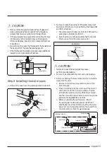
Page 10: ...lings require reinforcement use anchor holes For new ceilings use sunken inserts sunken anchors or other commercially available parts Concrete Anchorhole Insert Plughole Suspensionbolt Ø9 52orM10 Ceilingsupport CAUTION Purchase all the needed parts from the market Because the pattern sheet is made of paper it may shrink or stretch slightly due to temperature or humidity Therefore before drilling h...

Page 11: ...on bolts Uppernut Upperwasher Insertapad stopper Lowerwasher Lowernut 5 Insert a hanger bracket between the nuts fixed to each suspension bolt to hang the fan coil unit When installing the product be sure to install the piping inside the ceiling When an existing ceiling is used install the piping inside the ceiling before installing the fan coil unit Padstopper Bracket 6 Tighten the nuts to firmly...

Page 12: ...fixed CAUTION If dust or paint enters the unit it may degrade the product performance or cause product malfunction Step 5 Purging inert gas from the fan coil unit The fan coil unit comes with nitrogen gas inert gas charged at the factory Therefore all inert gas must be purged before connecting the water piping Open the sealed tube at the end of the piping The gas in the piping comes out Wateroutle...

Page 13: ...te the pipes After confirming that there is no leakage from the water inlet and outlet pipes and the drain pipe insulate all of them First insulate the 2 way electric valve before insulating the water inlet and outlet pipes Covered by the installation site Afterthe valve insulation is completed insulate the water inlet and outlet pipes and the drain pipe a Choose insulation materials suitable fort...

Page 14: ...itions When installing the piping inside a ceiling where there is a lot of water inflow and cannot be cooled locations near a corridor and entrance of a dormitory or an efficiency apartment Locations with a high humidity due to poor ventilation in the piping installation space Semi basement rooms NOTE If you are unclear about which insulation you should choose choose the one forthe high humidity c...

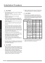
Page 15: ...r labels IN and OUT attached The water pipe inlet label is printed with IN and the water pipe outlet label with OUT Note that the airvent valve is attached to the side where you can find the water pipe outlet Appearance OUT outlet IN inlet CAUTION Failure to connect thewaterpipes maycause performance degradation Be sure to insulate both the inlet and outlet pipings 3 Before connecting the water pi...

Page 16: ...ow flow rates may cause performance degradation or product malfunction 4 Wind Teflon tape 10 to15 times around the threads of the water pipe inlet outlet Flexible tube of the fan coil unit in the thread direction CAUTION When connecting the pipes tighten sufficientlywith a monkeywrench and a torque wrench as shown in the figure above Failure to do so may cause water leakage When operating the prod...

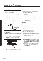
Page 17: ...ition of the connection port may differ depending on the fan coil unit model 2 Fix the drain pipe to the opposite end of the flexible hose Fix the connection port of the flexible hose and the drain pipe PVC with adhesive for PVC Afterthe adhesive for PVC is completely hardened check whetherwater leaks from the connection part Water pipe specifications Slim1 way cassette Small VP20 OD ø 26 ID ø 20 ...

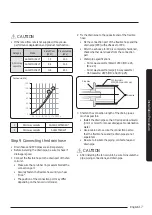
Page 18: ...fan coil unit is parallel to the ceiling 1 If the slope of the drain pipe is less than1 100 be sure to install an airvent at the inlet of each drain hole to smooth the flow of condensation water 2 If the drain pipe is installed higherthan the connection port install the drain pipe verticallywithin a distance of 300 mm from the flexible hose connection port Slim1 way cassette However because the wa...

Page 19: ...prohibited Make sure that the maximum bending angle does not exceed 30 Upward slope is prohibited Concentrated drainage Fullthreadbolthanger Connecttothemaindrainpipe Airventofthefancoilunit 1000to1500mm Mainairvent mustbeinstalled 20mmormore 550mmorless Centralizedhorizontaldrainpipe morethan1 100slope 1 If 3 or more fan coil units are installed install the main airvent at the front of the farthe...

Page 20: ... mode NOTE Only in the Cool mode you can check the correct operation of the drain pump When the electric cable connection is not completed Remove the control box cover of the fan coil unit Connect the power supply single phase 220 to 240V to the L and N terminals Reassemble the control box cover and turn on the fan coil unit NOTE When the float switch is not detected due to insufficient water on t...

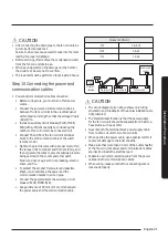
Page 21: ...to prevent outside pressure being exerted on the covers and other parts Failure to do so may result in overheating electric shock and fire To protect the product from water and possible shock you should keep the power and the communication cables in an iron pipe Connect the power cable to the auxiliary circuit breaker ELCB MCCB ELB Keep a distance of 50 mm or more mm between the power cable and th...

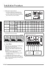
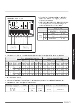
Page 22: ... 6 5 20 4 3 0 2 0 0 9 3 Specifications of the terminal blocks Unit mm AC power M4 screw Communication M3 screw Communication M3 5 screwELB 11 13 18 6 62 7 62 10 7 5 9 0 13 8 CAUTION When installing the product be sure to install a 2 way electric valve on the waterinlet pipe When connecting a 2 way electric value be sure to check the correct sub PBA terminals as shown in the figure below Incorrect ...

Page 23: ...ws SEG22 0 Cooling Heatingsynchronizingsignal SEG22 1 Cooling Heatingsignalseparated SEG15 0 SEG15 1 SEG15 0 SEG15 1 Valve Common terminal Optional terminal Cooling T ON Heating T ON Operation OFF Cooling T ON Heating T ON Operation OFF Cooling T ON Heating T ON Operation OFF Cooling T ON Heating T ON Operation OFF Valve1 N NO ON ON OFF OFF OFF ON ON OFF OFF OFF ON ON NC OFF OFF ON ON ON OFF OFF O...

Page 24: ...s fastened to the terminal øk Distance between fan coil units m Ak Thickness of the power cable mm ik Current between fan coil units A n k 1 Installation example Total power cable length L 100 m initial pull in current i 10 A running current of each unit 1 A total10 fan coil units are installed Coef 35 6 Lk ik 10 of input voltage V 1000 Ak n k 1 ELB MCCB 10 A 0 m 10 m 20 m 100 m Fancoilunit Fancoi...

Page 25: ...on tube 3 Insert both sides of core wire of the power cable into the connection sleeve Method1 Push the core wire into the sleeve from both sides Method 2 Twist the wire cores together and push it into the sleeve Method1 Connectionsleeve Connectionsleeve Method2 CAUTION If cable wires are connected without using connecting sleeves theircontact area becomes reduced or corrosion develops on the oute...

Page 26: ... extending the electric wire please DO NOT use a round shaped Pressing socket Incomplete wire connections can cause electric shock or a fire Step12 Setting the fan coil unit addresses and installation options The fan coil unit address setting and installation options are set with the remote control option You cannot set both of the fan coil unit addresses and the installation options in a batch se...

Page 27: ... SEG24 Take the steps presented in the following table Steps Remote control display 1 Set the SEG2 and SEG3 values a Set the SEG2 value by pressing the Low Fan button repeatedly until the value you want to set appears on the remote control display SEG2 b Set the SEG3 value by pressing the High Fan button repeatedly until the value you want to set appears on the remote control display When you pres...

Page 28: ...EG10 values a Set the SEG9 value by pressing the Low Fan button repeatedly until the value you want to set appears on the remote control display SEG9 b Set the SEG10 value by pressing the High Fan button repeatedly until the value you want to set appears on the remote control display When you press the Low Fan or High Fan button values appear in the following order SEG10 8 Press the Mode button He...

Page 29: ...alues a Set the SEG16 value by pressing the Low Fan button repeatedly until the value you want to set appears on the remote control display SEG16 b Set the SEG17 value by pressing the High Fan button repeatedly until the value you want to set appears on the remote control display When you press the Low Fan or High Fan button values appear in the following order SEG17 14 Press the Mode button Dry a...

Page 30: ... you want to set appears on the remote control display When you press the Low Fan or High Fan button values appear in the following order SEG22 18 Press the Mode button Heat and Off appear on the remote control display 19 Set the SEG23 and SEG24 values a Set the SEG23 value by pressing the Low Fan button repeatedly until the value you want to set appears on the remote control display SEG23 b Set t...

Page 31: ...ofhotwaterheater Dewremovaloperationin Wind Freemode AutoEvaporatorDrying fanmode Autofansmart comfortablemode SEG13 SEG14 SEG15 SEG16 SEG17 SEG18 2 Useofexternal control Externalcontroloutput Externalheateroutput Cooling operationoutput Cooling outputbyexternalequipment S Plasmaion Buzzercontrol Maximumfilterusagetime SEG19 SEG20 SEG21 SEG22 SEG23 SEG24 3 Individualcontrolwith remotecontrol Heati...

Page 32: ...il Indication Detail Indication Detail Indication Detail Indication Detail Indication Detail Useof external temperature sensor Minimizingfan operationwhen thermostatisoff 0 2 0 0 Disuse Disuse 0 Disuse 0 Disuse 1 Use Disuse 2 Disuse Heating Use 1 3 Use Heating Use 1 1 Compensation ofthefan RPM 4 Disuse Cooling Use 1 5 Use Cooling Use 1 6 Disuse Use 1 1 Use 7 Use Use 1 8 Disuse Cooling Lowest fansp...

Page 33: ...heblade Useeveryfanmode Disuse 3 Use 2 6 Maintainbladestatus inWind Freemode UseonlyWind Free mode Disuse 7 Coolingoperationby openingtheblade UseonlyWind Free mode Disuse Option SEG13 SEG14 SEG15 SEG16 SEG17 SEG18 Function Page Useofexternal control Externalcontroloutput Externalheater output Coolingoperationoutput Cooling outputbyexternalequipment S Plasmaion Buzzercontrol Maximumfilterusage tim...

Page 34: ...utput 2 The fan is turned on continuallywhen the external heater is turned on 3 The fan is turned off when the external heater is turned on with cooling only fan coil unit à ϩ ʪ ɇ ϑ ϑʪϩ ϩͱ ͱ ͱθ ʀͱͱ ͱ ц ɇ ʀͱ Ї ϩ ɵц ϑʪϩϩ ϩ ʪ Ɗk ߪॉߤ ͱθ Ɗk ߢߦॉߤࡡ цͱЇ ʪʪʒ ϩͱ Їϑʪ ɇ ʪуϩʪθ ɇ sensor orwired remote control sensorto detect indoortemperature exactly 4 Output occurs when operating in the Cool or Dry mode 5 An E...

Page 35: ...iablewhenusinghotwaterheater orexternalheater 1 Indications anddetails Indication Detail Indication Detail Indication Detail Indication Detail Indication Detail Indication Detail HeaterOnoffset temperature HeaterOn delaytime 2 0 0 0 factory default Normal Close 0 Close 0 Installed 0 Atthesametime withthermoon Immediately 1 1 1 Atthesametime withthermoon 10min 2 2 2 Atthesametime withthermoon 20min...

Page 36: ...peed B Use Highspeed Use Highspeed 1 Disuse Group controlusing remote control 2 1 Disuse 4 1 Thecooling andheating signalsaresent separately C Use Highspeed Disuse D Use Highspeed Use Usersetsthe airspeed E Use Highspeed Use Highspeed F Use Highspeed Use Highspeed 1 Heater operation when the 02 series installation option SEG9 Use of hot water heater is set to Use orthe 02 series installation optio...

Page 37: ...rol twice Make sure that this command is received by the fan coil unit When it is successfully received you can hear a short sound from the fan coil unit If the command is not received press the Power button again 7 Check whetherthe fan coil unit operates in accordance with the option values you have set Reset the fan coil unit by disconnecting and then reconnecting the power cable of the fan coil...

Page 38: ...etails Indication Detail Indication Detail Indication Detail Indication Detail Indication Detail Indication Detail 0 D Option type 1to6 Tensdigit value 0to9 Unitsdigit value 0to9 Newvalue 0toF NOTE To change the value of a position of the fan coil unit address set SEG3 to A To change the value of a position of the fan coil unit installation options set SEG3 to 2 Example Changing the Buzzer control...

Page 39: ... unit Using the operation modes and the functions Cleaning the fan coil unit and replacing the filter CAUTION Forthe test run be sure to operate each fan coil unit separately to secure S NET data After installation test run and delivery tell the userto store the user manual and this installation manual in a safe place CAUTION Operating precautions Be sure to operate heat sources chiller boiler aft...

Page 40: ...om the relay E102 3 Errorthat relay tracking continued for 3 minutes E202 4 Communication errorthat the actual number of installed FCUs differs from the number detected by tracking E201 5 Error due to duplicated communication addresses E108 6 Errorthat communication addresses are not yet determined E109 Communication errors otherthan the errors listed above Errors detected by the self diagnosis X ...

Page 41: ...41 English Appendix Memo ...

Page 42: ...42 Memo English Appendix ...

Page 43: ...43 English Appendix ...

Page 44: ...DB68 09309A 00 ...

Reviews: