21
English
Installation Pr
oc
edur
e
CAUTION
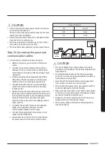
• After connecting the drain pipe to the fan coil unit, be
sure to perform a leak test.
Failure to do so may cause water to leak into the room,
leading to property damage.
• Before servicing, first remove the condensation water
from the fan coil unit drain pan.
• When pouring water on the drain pan or the hole for
the drain test, be sure not to overflow.
• The leak test must be performed for at least 24 hours.
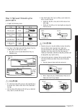
Step 10 Connecting the power and
communication cables
1
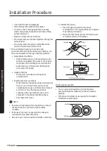
Power and communication cable connection
• Before wiring work, you must turn off all power
source.
• Connect the power and communication cables
between the fan coil units in the electrical panel
within maximum length so that the voltage drop is
under 10%.
• Install an auxiliary circuit breaker (ELCB, MCCB,
ELB) with sufficient capacity by considering the
number of fan coil units to be connected to it.
• Connect F3 and F4 of the fan coil unit terminal
block to the communication cable of the wired
remote control.
• Tighten the electric wires with a proper tool within
the torque limit to connect and fix them firmly, and
then organize the wires to prevent outside pressure
being exerted on the covers and other parts.
Failure to do so may result in overheating, electric
shock, and fire.
• To protect the product from water and possible
shock, you should keep the power and the
communication cables in an iron pipe.
• Connect the power cable to the auxiliary circuit
breaker (ELCB, MCCB, ELB).
• Keep a distance of 50 mm or more mm between
the power cable and the communication cable.
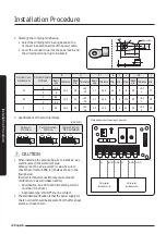
Torque limit (N
࡛
m)
M3
0.5~0.75
M3.5
0.8~1.2
M4
1.2~1.8
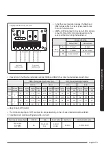
Fan coil unit 1
Fan coil unit 2
Fan coil unit 3
Wired remote
control
or
MCCB+
ELB
* Must be
installed.
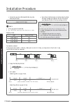
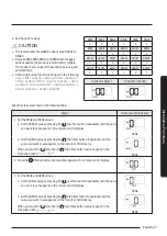
CAUTION
• The circuit diagram given above shows only wiring
schematic, and the details of the actual installation are
not presented.
• The standard specification is that the power supply
for the fan coil unit should be separate from that for a
heat source such as a chiller.
• Never branch the terminal block power supply cable
from one fan coil unit to two fan coil units.
• When peeling the power cable, use a special tool for it
to prevent damage to the inner sheaths.
• Make sure that more than 20 mm of the outer sheaths
of the fan coil unit's power and communication cables
are inserted inside the electrical part.
• Separate each communication cable from the power
cable and other communication cables.
• When wiring, make sure that the connecting wire is
loosened properly.
Summary of Contents for AGTN1DKH Series
Page 41: ...41 English Appendix Memo ...
Page 42: ...42 Memo English Appendix ...
Page 43: ...43 English Appendix ...
Page 44: ...DB68 09309A 00 ...

