12
Installation Procedure
English
Installation Pr
oc
edur
e
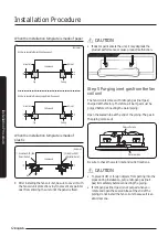
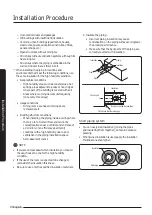
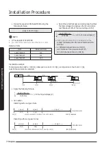
When the installation template is made of paper
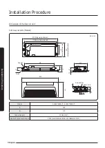
(Unit: mm)
Slim 1 way cassette (Small, Wind-free panel)
Slim 1 way cassette (Medium/Large, Wind-free panel)
Indoor unit
Indoor unit
Air outlet
Air outlet
Air inlet
Air inlet
6.0
10
Jig
Jig
Ceiling
Ceiling
8.0
10
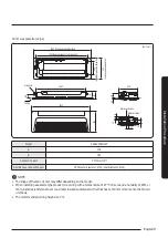
When the installation template is made of
plastic
(Unit: mm)
Indoor unit
幩
Wind-Free MID /
LRG (Inlet / Outlet)
幩
Wind-Free MID / LRG
(Inlet / Outlet)
10
Jig
10
8
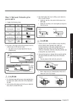
After installing the fan coil unit, be sure to cover it with
the fan coil unit protection vinyl to prevent any paint or
dust from entering the unit until the panel is fixed.
CAUTION
• If dust or paint enters the unit, it may degrade the
product performance or cause product malfunction.
Step 5 Purging inert gas from the fan
coil unit
The fan coil unit comes with nitrogen gas (inert gas)
charged at the factory. Therefore, all inert gas must be
purged before connecting the water piping.
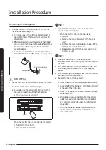
Open the sealed tube at the end of the piping. The gas in
the piping comes out.
Water outlet side
Water inlet side
Be sure to check the water inlet and outlet locations.
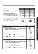
CAUTION
• To prevent dirt or foreign objects from getting into the
pipes during installation, purge nitrogen gas (inert
gas) immediately before connecting the piping.
• If nitrogen gas (inert gas) is not purged when you
rotate and open the sealed tubes at the end of the
piping, do not install the fan coil unit because it is an
abnormal one.
Summary of Contents for AGTN1DKH Series
Page 41: ...41 English Appendix Memo ...
Page 42: ...42 Memo English Appendix ...
Page 43: ...43 English Appendix ...
Page 44: ...DB68 09309A 00 ...


