24
Installation Procedure
English
Installation Pr
oc
edur
e
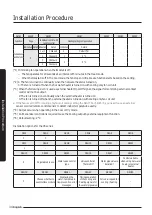
• Decide the capacity of ELB and MCCB using the
following formula.
ǹࣈࣉ॔ߣߤߧǹߣߣǹॣ̈
NOTE
• X: The capacity of ELB, MCCB
•
॥̈ࡠƊЇ͔ͱ˙ϩ˵ʪθɇϩʪʒʀЇθθʪ͝ϩϑͱ˙ϩ˵ʪ˙ɇ͝ʀͱ̷̈Ї̈͝ϩϑ
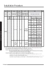
Rated currents
Mode
Rated current (A)
AG026TN1DKH*
0.14
AG032TN1DKH*
0.19
AG042TN1DKH*
0.29
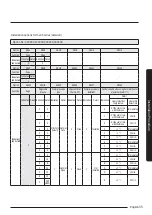
• Select the cable thickness and wiring length so that
the total voltage drop between the fan coil units is
less than about 10% of the input voltage (220 V).
॥࣍
Coef × 35.6 × L
k
× i
k
) < 10 % of input voltage [V]
1000×Ak
࢘Aͱʪ˙ࡠΧΧθͱӱ͔ɇϩʪ̷цߢࢋߦߦ̈͝ʀͱ͝ϑ̈ʒʪθɇϩ̈ͱ͝ͱ˙ϩ˵ʪ
contact resistance when the wire is fastened to the
terminal
࢘ø
k
: Distance between fan coil units [m],
Ak: Thickness of the power cable [mm²]
ik: Current between fan coil units [A]
n
k=1
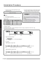
Installation example
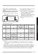
Total power cable length L = 100 [m], initial pull-in current i = 10 [A], running current of each unit = 1 [A],
total 10 fan coil units are installed.
॥࣍
Coef × 35.6 × L
k
× i
k
) < 10 % of input voltage [V]
1000×Ak
n
k=1
ELB
MCCB
10 [A]
0 [m]
10 [m]
20 [m]
100 [m]
Fan coil unit
Fan coil unit
Fan coil unit
9 [A]
1 [A]
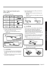
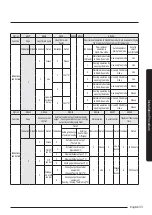
• Apply the following formula.
• Calculation
Installing with one type of wire
Installing with two types of wires
2.5 [mm²]
-2.2 [V]
220 [V]
208.8 [V]: Applicable
-(2.2 + 2.0 + 1.8 + 1.5 + 1.3 + 1.1 + 0.9 + 0.7 + 0.4 + 0.2) = -11.2 [V]
-2.0 [V]
2.5 [mm²]
············ 2.5 [mm²] ············
Within 198 V to 242 V
4.0 [mm²]
4.0 [mm²]
············ 2.5 [mm²] ············
Within 198 V to 242 V
-1.4 [V]
-1.2 [V]
220 [V]
-(1.4 + 1.2 + 1.8 + 1.5 + 1.3 + 1.1 + 0.9 + 0.7 + 0.4 + 0.2) = -10.5 [V]
209.5 [V]: Applicable
Summary of Contents for AGTN1DKH Series
Page 41: ...41 English Appendix Memo ...
Page 42: ...42 Memo English Appendix ...
Page 43: ...43 English Appendix ...
Page 44: ...DB68 09309A 00 ...

