background image


84 

APPENDIX  


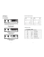
A. Connectors 


RS-232

POWER

DK

ON


 When the Dip Switch is “ON” on the Serial Interface Board, 

  DTR and RTS are connected each other. 


SRP-370/372 Connector 

( Serial Interface ) 


POWER

DK

PARALLEL


SRP-370P/372P Connector 

( Parallel Interface ) 


POWER

DK

USB


SRP-370U/372U Connector 

( USB Interface )


Power 

Supply 

Connector

Drawer 

Kick-out 

Connector

Interface Connector 

Power 

Supply 

Connector

Drawer 

Kick-out 

Connector

Interface Connector 

Power 

Supply 

Connector

Drawer 

Kick-out 

Connector

USB Connector 


85

RS-232C Cable Connection 


Interface Connector 


Serial Interface (RS-232) 

Pin No. Signal name

Direction Function 

1 FG 

-  Frame 

Ground 

2 TxD 

Output 

Transmit 

Data 

3 RxD 

Input 

Receive 

Data 

RTS 

Output 

Ready To Send 

CTS 

Input 

Clear To Send 

DSR 

Input 

Data Set Ready 

7 SG 

-  Signal 

Ground 

20 

DTR 

Output 

Data Terminal Ready 


Summary of Contents for 2 COLOR THERMAL PRINTER SRP-370

Page 1: ...ed multi outlets You must use only the supplied adapter It is dangerous to use other adapters Do not pull the cable to unplug This can damage the cable which is the origin of a fire or a breakdown of the printer Keep the plastic bag out of children s reach If not a child may put the bag on his head Do not plug in or unplug with your hands wet You can be electrocuted Do not bend the cable by force ...

Page 2: ...esidential area is likely to cause harmful interference in which case the user will be required to correct the interference at his own expense Notice Canada This Apparatus complies with class A limits for radio interference as specified in the Canadian department of communications radio interference regulations Get appareil est conforme aux normes class A d interference radio tel que specifier par...

Page 3: ... 10 SETTING THE MEMORY SWITCHES 15 CHAPTER 2 HEXADECIMAL DUMPING 17 CHAPTER 3 THE SELF TEST 18 CHAPTER 4 CODE TABLE 19 CHAPTER 5 CONTROL COMMANDS LIST 36 APPENDIX 84 A CONNECTORS 84 RS 232C Cable Connector 85 Interface Connector 85 Drawer Connector 87 B NOTES 87 C SPECIFICATION 88 5 Chapter 1 Setting Up the Printer 1 1 Unpacking Your printer box should include these items If any items are damaged ...

Page 4: ...e interface cable 1 Plug the cable connector securely into the printer s interface connector 2 Tighten the screws on both sides of the cable connector 3 Attach the other end of the cable to the computer 1 4 Connecting the Drawer WARNING Use a drawer that matches the printer specification Using an improper drawer may damage the drawer as well as the printer CAUTION Do not connect a telephone line t...

Page 5: ... power supply matches that of your electrical outlet 3 Plug in the power supply s cable as shown below Notice that the flat side of the plug faces down Notes To remove the DC cable connector make sure that the power supply s power cord is unplugged then grasp the connector at the arrow and pull it straight out 9 1 6 Installing or Replacing the Paper Roll 1 Make sure that the printer is not receivi...

Page 6: ... miss loading 11 1 7 Adjustments and Settings 1 It has 2 features Paper end and Black mark For detecting Paper End it must be positioned at a Position in drawing and it is a factory default setting For detecting Black mark printed on the paper it must be moved to b position 2 Optical density O D must be higher than 0 6 in density to secure a standard working condition Make sure if the density of p...

Page 7: ...s Serial Interface RS 232C RS 485 Specification DIP Switch Set 1 Functions Switch No Function ON OFF Default SW1 1 OFF SW1 2 Baud Rate Selection Refer to below Table OFF SW1 3 Handshaking Hardware DTR DSR Software Xon Xoff OFF SW1 4 Reserved OFF SW1 5 Cutter Function Disable Enable OFF SW1 6 Paper 2 Color Mono OFF SW1 7 Reserved OFF SW1 8 Reserved ON Baud rate selection Dip Switch Set 2 Functions ...

Page 8: ...Disabled Application Ignores Auto Cutter error for continuous printing Auto Cutter Enable Disable selection 15 1 10 Setting the Memory Switches This printer has Memory Switch set which is software switches Memory Switch set has MSW1 MSW2 MSW8 MSW9 Customize value Serial communication condition Memory Switch setting utility can change the Memory Switch set to ON or OFF as shown in the table below d...

Page 9: ...W9 8 MSW9 7 MSW9 6 Baud Rate OFF OFF OFF 9600 OFF OFF ON 19200 OFF ON OFF 38400 OFF ON ON 57600 ON OFF OFF 115200 17 Chapter 2 Hexadecimal Dumping This feature allows experienced users to see exactly what data is coming to the printer This can be useful in finding software problems When you turn on the hexadecimal dump function the printer prints all commands and data in hexadecimal format along w...

Page 10: ... following and pause The PAPER LED light blinks Self test printing Please press the FEED button 5 Press the FEED button to continue printing The printer prints a pattern using the built in character set 6 The self test automatically ends and cuts the paper after printing the following COMPLETED The printer is ready to receive data as soon as it completes the self test 19 Chapter 4 Code Table The f...

Page 11: ...20 Page 1 Katakana 21 Page 2 PC850 Multilingual ...

Page 12: ...22 Page 3 PC860 Portuguese 23 Page 4 PC 863 Canadian French ...

Page 13: ...24 Page 5 PC 865 Nordic 25 Page 16 WPC1252 Latin 1 ...

Page 14: ...26 Page 17 PC866 Cyrillic 2 27 Page 18 PC852 Latin2 ...

Page 15: ...28 Page 19 PC858 Euro 29 Page 22 PC864 Arabic ...

Page 16: ...30 Page 23 Thai character code 42 31 Page 24 WPC1253 Greek ...

Page 17: ...32 Page 28 WPC1251 Cyrillic 33 Page 29 PC737 Greek ...

Page 18: ...34 Page 255 Space Page 35 International Character Set ...

Page 19: ... relative print position ESC a Select justification ESC c 3 Select paper sensor s to output paper end signals ESC c 4 Select paper sensor s to stop printing ESC c 5 Enable disable panel buttons 37 Command Name ESC d Print and feed n lines ESC p General pulse ESC t Select character code table ESC Turn upside down printing mode on off FS p print NV bit image FS q Define NV bit image GS Select charac...

Page 20: ...e in page mode ASCII FF Hex 0C Decimal 12 In page mode prints the data in the print buffer collectively and returns to standard mode 39 CR Name Format Description Notes Print and carriage return ASCII CR Hex 0D Decimal 13 When automatic line feed is enabled this command functions the same as LF When automatic line feed is disabled this command is ignored CR The automatic line feed is ignored with ...

Page 21: ... Paper roll near end sensor paper adequate 3 On 08 8 Paper roll near end sensor paper near end 4 On 10 16 Fixed Off 00 0 Paper roll near end sensor paper present 5 On 20 32 Paper roll near end sensor paper not present Off 00 0 Paper roll near end sensor paper present 6 On 40 64 Paper roll near end sensor paper not present 7 Off 00 0 Fixed Notes If print data includes a character string with this c...

Page 22: ...command is encountered the printer will not continue to process anything To recover the printer to print again it is necessary to turn the power on again or execute a hardware reset If print data includes a character string with this command the printer performs the command User must consider this For example Bit image data accidentally might include a data string with this command Do not embed th...

Page 23: ...tion and the absolute print position in reference to the left margin The distance from the beginning of the line to the left margin is nL nH x 256 x vertical or horizontal motion units ESC n Name Format Range Default Description Select cancel user defined character set ASCII ESC n Hex 1B 25 n Decimal 27 37 n 0 n 255 n 0 Select or cancels the user defined character set When the LSB of n is 0 the us...

Page 24: ...mal 27 45 n 0 n 2 48 n 50 n 0 Turn underline mode on or off based on the following values of n n Function 0 48 Turns off underline mode 1 49 Turns on underline mode set at 1 dot width 2 50 Turns on underline mode set at 2 dot width 47 ESC 2 Name Format Description Select default line spacing ASCII ESC 2 Hex 1B 32 Decimal 27 50 For SRP 370 Sets the current line spacing to approximately 4 23mm 1 6 F...

Page 25: ...9 n 0 n 255 n 0 Turns emphasized mode on or off When the LSB of n is 0 emphasized mode is turned off When the LSB of n is 1 emphasized mode is turned on 49 ESC G n Name Format Range Default Description Turn double strike mode on off ASCII ESC G n Hex 1B 47 n Decimal 27 71 n 0 n 255 n 0 Turns double strike mode on or off When the LSB of n is 0 double strike mode is turned off When the LSB of n is 1...

Page 26: ... 51 n Print Direction Starting Position 0 48 Left right Upper left 1 49 Bottom to top Lower left 1 50 Right left Lower right 3 51 Top bottom Upper right ESC V n Name Format Range Default Description Turn 90 clockwise rotation mode on off ASCII ESC V n Hex 1B 56 n Decimal 27 86 n 0 n 2 48 n 50 n o Turn 90 clockwise rotation mode on off in standard mode When the paper roll is selected n Function 0 4...

Page 27: ...ormat Range Default Description Select justification ASCII ESC a n Hex 1B 61 n Decimal 27 97 n 0 n 2 48 n 50 n 0 In standard mode aligns all the data in one line to the position specified by n as follows n Justification 0 48 Left justification 1 49 Centering 2 50 Right justification 53 ESC c 3 n Name Format Range Default Description Select paper sensor s to output paper end signals ASCII ESC c 3 n...

Page 28: ...ecifies the pulse ON time as t1 x 2ms and t2 specifies the pulse OFF time as t2 x 2ms If t2 is smaller than t1 OFF time is set as t1 x 2ms 55 ESC t n Name Format Range Default Description Select character code table ASCII ESC t n Hex 1B 74 n Decimal 27 116 n 0 n 5 16 n 24 27 n 30 n 255 For model without Thai character support n 0 For model with Thai character support n 20 Selects a page n from the...

Page 29: ...lete all NV graphics data then define the bit image data with this command Frequent write command executions by this command may damage to the NV memory Therefore it is recommended to write to the NV memory 10 times or less a day During processing of this command the printer is BUSY while writing the data to the NV bit image memory and stops receiving data Therefore it is prohibited to transmit da...

Page 30: ...l time command b specifies enable or disable If bit image data accidentally includes a character string with this command it is recommended to use this command in advance to disable the real time command 59 GS E pL pH fn parameter Name Description Customize NV memory area Customize the NV user memory area The table below explains the functions available in this command Executes commands related to...

Page 31: ...fn 3 a 1 2 8 9 b 48 49 50 Msw2 1 Msw2 2 and Msw 8 8 are set to On b 49 and all other switches are set to Off b 48 61 Description Change the memory switch specified by a to the values specified by b When b 48 the applicable bit is turned to Off When b 49 the applicable bit is turned to On When b 50 the applicable bit is not changed When a 1 the memory switch 1 is set as follows Bit Setting value Fu...

Page 32: ...ff Hexadecimal 30H Decimal 48 On Hexadecimal 31H Decimal 49 63 Function 11 GS E pL pH fn a d1 dk fn 11 Format Range Default Description Notes ASCII GS E pL pH fn a d1 dk Hex 1D 28 45 pL pH fn a d1 dk Decimal 29 40 69 pL pH fn a d1 dk 3 pL pH x 256 65535 0 pL 255 0 pH 255 fn 11 1 a 4 48 d 57 1 k 6 When a 1 d1 dk 19200 When a 2 d 48 When a 3 d 48 When a 4 d 56 Sets the communication conditions of th...

Page 33: ...al 29 40 76 p1 p2 p3 p4 m fn parameter In the description below GS L is used for the explanation Note that GS L and GS 8 L have the same Function If the parameter of each format exceeds 65533 bytes use GS 8 L Processes graphics data according to the function code fn fn Format Function No Function 0 48 GS L pL pH m fn Function 48 Transmits the NV graphics memory capacity 2 50 GS L pL pH m fn Functi...

Page 34: ...1 8 bytes NUL 00H 0 1 byte The number of bytes of remaining memory is converted to character codes corresponding to decimal data then transmitted from the MSB The data length is variable 67 Function 64 GS L pL pH m fn d1 d2 fn 64 Format Range Description ASCII GS L pL pH m fn d1 d2 Hex 1D 28 4C pL pH m fn d1 d2 Decimal 29 40 76 pL pH m fn d1 d2 pL pH x 256 4 pL 4 pH 0 m 48 fn 64 d1 75 d2 67 Transm...

Page 35: ... The total capacity of the UV user memory is selectable as any one of 0 64K 128K 192K 256K 320K 384K bytes with GS E The default value is 384KB Defines the raster graphics data in the NV graphics area b specifies the number of the color of the defined data xL xH specifies the defined data in the horizontal direction to xL xH x 256 dots xL xH specifies the defined data in the vertical direction to ...

Page 36: ... color can be defined only once 71 GS M pL pH fn m Name Description Customize printer Protects or recovers values or data set or defined in the active area by commands fn Function No Descriptions 1 49 Function 1 Copies the settings stored in the active area to the storage area save settings 2 50 Function 2 Copies the settings stored in the storage area to the storage area load settings 3 51 Functi...

Page 37: ...he color specified by m m Color 49 Color 1 50 Color 2 Color 1 means black high level of energy in the specified two color thermal paper Color 2 means red low level of energy in the specified two color thermal paper 73 GS x y d1 d x x y x 8 Name Format Range Description Define downloaded bit image ASCII GS x y d1 d x x y x 8 Hex 1D 2A x y d1 d x x y x 8 Decimal 29 42 x y d1 d x x y x 8 1 x 255 1 y ...

Page 38: ...version ID Depends on firmware version n specifies the printer information n Printer ID type ID 65 Firmware version Depends on firmware version 66 Manufacturer BIXOLON 67 Printer name SRP 370 372 75 GS L nL nH Name Format Range Default Description Set left margin ASCII GS L nL nH Hex 1D 4C nL nH Decimal 29 76 nL nH 0 nL 255 0 nH 255 nL nH x 256 0 nL 0 nH 0 Sets the left margin specified by nL and ...

Page 39: ... Full cut or one point left uncut cannot be changed by software 77 GS W nL nH Name Format Range Default Description Set printing area width ASCII GS W nL nH Hex 1D 57 nL nH Decimal 29 87 nL nH 0 nL 255 0 nH 255 For SRP 370 nL nH x 256 512 nL 0 nH 2 for 80mm of the paper width nL nH x 256 384 nL 128 nH 1 for 60mm of the paper width nL nH x 256 360 nL 104 nH 1 for 58mm of the paper width For SRP 372...

Page 40: ... 7 Off 00 0 Fixed 79 Notes Reference When the cover is open while the printing is stopped the printer becomes offline Second byte printer information Bit Off On Hex Decimal Function Off 00 0 Not on online waiting status 0 On 01 1 During online waiting status Off 00 0 Panel button OFF 1 On 02 2 Panel button ON Off 00 0 No mechanical error 2 On 04 4 Mechanical error has occurred Off 00 0 No Auto Cut...

Page 41: ...ormat Range Description Notes Print bar code ASCII GS k m d1 dk NUL Hex 1D 6B m d1 dk NUL Decimal 29 107 m d1 dk NUL ASCII GS k m n d1 dn Hex 1D 6B m n d1 dn Decimal 29 107 m n d1 dn 0 m 6 k and d depend on the bar code system used 65 m 73 n and d depend on the bar code system used Selects a bar code system and prints the bar code For m Bar Code System Range of k Range of d 0 UPC A 11 k 12 48 d 57...

Page 42: ...h 0 1 yL yH x 256 4095 0 yL 255 0 yH 15 0 d 255 k xL xH x 256 x yL yH x 256 83 Description Prints a raster bit image in m mode m specifies the bit image mode For SRP 370 m Mode Vertical dot density Horizontal dot density 0 48 Normal 180 dpi 180 dpi 1 49 Double width 180 dpi 90 dpi 2 50 Double height 90 dpi 180 dpi 3 51 Quadruple 90 dpi 90 dpi For SRP 372 m Mode Vertical dot density Horizontal dot ...

Page 43: ... Connector Drawer Kick out Connector Interface Connector Power Supply Connector Drawer Kick out Connector Interface Connector Power Supply Connector Drawer Kick out Connector USB Connector 85 RS 232C Cable Connection Interface Connector Serial Interface RS 232 Pin No Signal name Direction Function 1 FG Frame Ground 2 TxD Output Transmit Data 3 RxD Input Receive Data 4 RTS Output Ready To Send 5 CT...

Page 44: ...nter 5V ND ND 36 Host nSelectIn 1284 Active 1284 Active USB Interface Pin No Signal Name Assignment Color Function Shell Shield Drain Wire Frame Ground 1 VBUS Red Host Power 2 D White Data Line D 3 D Green Data Line D 4 GND Black Signal Ground 87 Drawer Connector Pin No Signal name Direction 1 Frame ground 2 Drawer kick out drive signal 1 Output 3 Drawer open close signal Input 4 24V 5 Drawer kick...

Page 45: ...mm sec Receive Buffer Size 4K Bytes NOTE Printing speed may be slower depending on the data transmission speed and the combination of control commands Input voltage 100 240 VAC Frequency 50 60 Hz Supply voltage Output voltage 24 VDC Temperature 0 45 Operating 10 50 Storage Environmental Conditions Humidity 30 80 RH Operating 10 90 RH Storage Except for paper MCBF Mechanism Monochrome 70 000 000Lin...

Reviews: