background image

Tel: 886.2.2175 2930 Email: [email protected] 

www.salukitec.com


Keys 

Function 

Sweep 

Sweep settings. Include sweep point, sweep time settings. 

Marker 

Marker Functions 

Marker Fctn 

Marker analysis functions 

Marker-> 

Take marker as a reference to move the trace 

Peak 

Peak search functions 

Meas 

Measurement functions, spectrum, ACPR, OBW included 

Trig 

Trigger settings 

Demod 

Demodulation functions, AM/FM included 

Source 

Setting of the tracking source or normal source 

4.1.2


Input Keys 

S3531 has numeric keys, knob and navigation keys to do the input. 

4.1.2.1


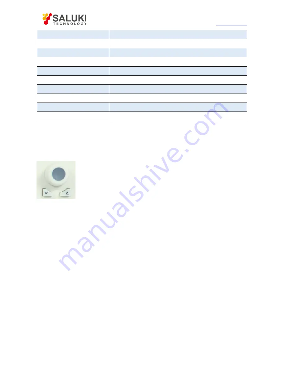
Knob and navigation keys 


Knob functions:   


When entering numbers, step up (clockwise) or down (anticlockwise) the instrument parameters as specified; 


To move the selection bar in the Focus area (such as list); 


To move markers or limit lines on the screen; 


When pressed, it has the same function with Enter key. 


Up/down key functions 


To increase or decrease instrument parameters in steps; 


To roll up and down the items in the list; 


To vertically move the selection bar in the table; 


To move the scroll bar in windows or dialogs with the vertical scroll bar. 

Summary of Contents for S3531 series

Page 1: ...S3531 Series Spectrum Analyzer User Manual Saluki Technology Inc...

Page 2: ...em Name Qty 1 Main Machine 1 Set 2 Power Cord 1 pcs 3 CD 1 pcs Options of the S3531 spectrum analyzer Option Number Item S3531 01 100kHz 1 5GHz 100kHz 3 2GHz tracking source S3531 02 Dual source track...

Page 3: ...ganization or individual or reproduced or transmitted for the purpose of making profit without its prior permission otherwise Saluki will reserve the right to investigate and affix legal liability of...

Page 4: ...n it shall be met before the next step Attention indicates important prompts and no danger It reminds the user to pay attention to a certain operation process operation method or similar situations No...

Page 5: ...1 3 Operating Environment 12 3 1 4 Electrostatic Protection 13 3 1 5 First Power Up 13 3 2 Routine Maintenance 14 4 Front and Rear Panels 8 4 1 Front Panel 8 4 1 1 Function Keys 8 4 1 2 Input Keys 9 4...

Page 6: ...ure 21 6 2 AMPT 23 6 3 BW 24 6 4 Detect 25 6 5 Demod 26 6 6 FILE 27 6 7 FREQ 28 6 8 Marker 30 6 9 Marker 32 6 10 Marker Function 33 6 11 Meas 34 6 12 PEAK 37 6 13 Print 38 6 14 SAVE 38 6 15 SOURCE 39...

Page 7: ...4 5 Menu Bar 53 8 Specification Details 56 8 1 Frequency 56 8 2 Amplitude 56 8 3 Input Output 56 8 4 RBW 57 8 5 DANL 0dB attenuation RBW 1Hz 57 8 6 Phase Noise 57 8 7 Sweep Time 57 8 8 Spurious Respon...

Page 8: ...or full span min 158dBm typ Phase noise 100 dBc Hz at 100 kHz offset Optional dual source tracking source and normal source up to 3GHz Standard pre amplifiers SCPI supported 1 3 Typical Applications E...

Page 9: ...Tel 886 2 2175 2930 Email sales salukitec com www salukitec com 9 Audio demodulation Scalar network measurement...

Page 10: ...packing container in shipping and avoid falling or violent collisions in moving which may cause damages to the device 2 Use AC DC adapter power cord shipped with the device to supply power charge to...

Page 11: ...ectric shock Use dry or moist soft cloth to clean the device Do not clean the internal of the device 4 Before using this device personnel need to be trained When using the device concentration is requ...

Page 12: ...fully whether the instrument has any damage during transportation If the instrument has obvious damage it is strictly forbidden to be powered on Please contact Saluki and we will repair or exchange it...

Page 13: ...as well as conductive floor mat and heel strap combination Both types when used together provide a significant level of ESD protection Among the two only the table mat and wrist strap combination prov...

Page 14: ...k other sides of the instrument and ensure no damage 6 Clean other sides of the instrument with a soft cloth Please pay attention to the ports and interfaces do not clean them and avoid any scratches...

Page 15: ...10 USB port 5 Power Button 6 Knob and navigation keys 4 1 1 Function Keys Keys Function AUTO Auto measurement System System settings Preset Preset the instrument FREQ Frequency settings Include Start...

Page 16: ...normal source 4 1 2 Input Keys S3531 has numeric keys knob and navigation keys to do the input 4 1 2 1 Knob and navigation keys Knob functions When entering numbers step up clockwise or down anticloc...

Page 17: ...no input field is active this key will cancel recently entered value and restore the previous value Therefore users can switch between two values such as frequency span 4 1 3 Enter key To terminate th...

Page 18: ...arbitrary signal Need to purchase option 001 4 2 Rear Panel Figure 4 2 S3531 Spectrum Analyzer Rear Panel No Description No Description 1 10MHz Reference IN OUT BNC 5 LAN port RJ45 2 External Tigger B...

Page 19: ...Tel 886 2 2175 2930 Email sales salukitec com www salukitec com 12 1 Display format 9 State bar 6 Time 14 Span 7 Marker 15 Sweep Time 8 Marker information 16 Soft Menu...

Page 20: ...ble or a pair of antennas Before any test please ensure power level of input signal should not exceed 30dBm 1W otherwise the instrument would be damaged 5 2 Continuous Signal Measurement 1 Set S1103 s...

Page 21: ...nals with equal amplitude and close frequency interval the top of one band pass filter waveform nearly covers another one making two signals like one If two signals of different amplitudes but close f...

Page 22: ...splayed on the spectrum analyzer to make the displayed amplitudes of two signals equal 3 Set up the spectrum analyzer to view signals Press Preset Press Freq Select Center Freq and input 1800 MHz Pres...

Page 23: ...of IF filters other than the bandwidth 3dB Squareness factor is defined as the ratio of 60dB bandwidth to 3dB bandwidth of the intermediate frequency filter as shown in Figure below Figure 5 5 Schemat...

Page 24: ...resolved as shown in Figure 4 6 Figure 4 6 30KHz RBW 4 Reduce the resolution bandwidth to view the small signals hidden Press BW Res BW Auto Man 1 kHz At this moment the half bandwidth is narrower tha...

Page 25: ...et key to return the instrument to default status 3 Set test frequency Press FREQ key Select Center FREQ and input 500MHz Press SPAN key Select Span and input 1MHz 4 Press BW key Select Res BW Auto Ma...

Page 26: ...tor and generates a 500MHz 10dBm continuous signal Example 1 Connect the signal generator output port to S3531 RF test port 2 Press Preset key to return the instrument to default status 3 Set test fre...

Page 27: ...uous signal Example 1 Connect the signal generator output port to S3531 RF test port 2 Press Preset key to return the instrument to default status 3 Set test frequency Press FREQ key Select Center FRE...

Page 28: ...Bm continuous signal Example 1 Connect the signal generator output port to S3531 RF test port 2 Press Preset key to return the instrument to default status 3 Set test frequency Press FREQ key Select C...

Page 29: ...nstrument to default status 3 Set test frequency Press FREQ key Select Center FREQ and input 500MHz Press Span key Select Span and input 10MHz 4 Enable the pre amplifier Press AMP key Select Ref level...

Page 30: ...xample the marker 1 is located at 300MHz and 10dBm signal which is the input signal Press Marker key Select Delta a Marker 2 is activated and it is a Delta marker the reference marker is Marker 1 Pres...

Page 31: ...r FREQ and input 500MHz Press SPAN key Select SPAN and input 5MHz Press BW key Select Res BW Auto Man and input 1kHz 4 Use Peak and Marker keys to do the analyze Press Peak key S3531 will search the M...

Page 32: ...Tel 886 2 2175 2930 Email sales salukitec com www salukitec com 20 Fig 5 15 TOI Distortion Measurement...

Page 33: ...and will give description of each menu option 6 1 Menu Structure This section provides the structure of all buttons and soft keys S3531 has following function keys on front panel Following paragraphs...

Page 34: ...alukitec com www salukitec com 22 SYSTEM TRACE TRIG In following paragraphs F1 F6 are corresponding keys to operate the menu shown in the screen Different menu levels will be shown in different colors...

Page 35: ...Maximum can be set to 39dB Preamplifier ON OFF Menu description to control the ON OFF status of the preamplifier Preamplifier is provided as a standard component Scale Div Menu description to select t...

Page 36: ...number keys step keys and knob The shaded character indicates the currently selected mode RBW Mode Def Count Menu description Manually change the RBW by step or continuously VBW Auto Manual Menu desc...

Page 37: ...to set the detector command for the currently selected trace as Normal i e display the measurement results of positive peak and negative peak at the same time to achieve display effect similar to the...

Page 38: ...can hear the audio output via the load speaker or a earphone Demod On Off Menu Description Turn On Off Audio analysis function Demod Mode Menu Description Select the audio input Volume Menu Descripti...

Page 39: ...Catalog Menu description View all saved screenshot or datafiles First Page Prev Page Next Page Last Page buttons are provided Type Menu description View files in different types Following types are p...

Page 40: ...requency Start Freq Menu description to enable the start frequency and set the signal spectrum analyzer into the start frequency stop frequency mode Use number keys stepping keys or knob to change the...

Page 41: ...e center frequency by 300MHz to 900MHz The shaded status of CF Step Auto Manual menu indicates whether the step is set as Auto or Manual When the step is under Manual select the Auto from CF Step Auto...

Page 42: ...marker to other traces Normal Menu description Create a new normal maker or change the active marker from a delta marker to a normal marker Normal marker will information is displayed on screen X axi...

Page 43: ...ukitec com 31 Off Menu description Turn off the selected marker All Off Menu description Turn off all markers Marker Table On Off Menu description to turn on off the marker table display Where there a...

Page 44: ...cription to set the Start Frequency equal to the Marker Frequency The menu changes the value of start frequency Marker Stop Menu description to set the Stop Frequency equal to the Marker Frequency The...

Page 45: ...normalizes the noise into 1Hz bandwidth near the active marker At that time the detector is under Sample Detector mode Freq Count Menu description to turn on or off marker Freq Count If there is no a...

Page 46: ...Tel 886 2 2175 2930 Email sales salukitec com www salukitec com 34 6 11 Meas...

Page 47: ...nnel Channel Power Menu description Turn on channel power measurement function Detailed settings to be done in Meas Setup The channel power is measured based on the channel bandwidth settings OBW Menu...

Page 48: ...ntal limit lines for amplitude Freq Line On Off Menu Description Turn on off the vertical limit lines for frequency Window Sweep On Off Menu Description If turn on window sweep only the trace in the l...

Page 49: ...urrent test trace Right Peak Menu description to search for the peak to the right of the current test trace marker position Left Peak Menu description to search for the peak to the left of the current...

Page 50: ...p the printing settings user can select the paper size the paper orientation etc 6 14 SAVE Save function can help user to save measurement data like screenshot or trace data Meanwhile it can also save...

Page 51: ...ut the submenu for tracking generator Trac Gen On Off Menu description to turn on off the tracking generator Out Level Menu description to set the output power level of tracking generator Net Meas Men...

Page 52: ...t and sweep time Normalize Menu description To normalize the test result Sig Gen Pop out the submenu for signal generator settings Sig Gen On Off Menu description to turn on off the build in signal ge...

Page 53: ...pan Menu description the span can be set by number keys stepping keys or knob Use number keys or select Zero Span to set the span as zero Full Span Menu description to set the signal spectrum analyzer...

Page 54: ...be set manually When it is under Auto mode the sweep time will be automatically coupled based on resolution bandwidth span and video bandwidth The sweep time is coupled with the sweep type resolution...

Page 55: ...the serial port like IP address etc PowerOn Preset Menu description To customize the preset configuration Language Menu description To change the language Date Time Menu description To change the time...

Page 56: ...ld Menu description to set the current trace processing method as maximum hold i e the new trace data will be assigned with maximum value of previous measured trace data Min Hold Menu description to s...

Page 57: ...rrent trace and save the result in trace register 2 and display 2 3 Menu description Exchange the data in trace register 2 and trace register 3 and display 1 3 Menu description Put data in trace regis...

Page 58: ...ion Set the trigger mode S3531 supports both internal and external trigger Auto Run Menu Description Free run Video Menu Description Set the trigger mode to Video trigger External Menu Description Tig...

Page 59: ...7 32bit LAN connection Win XP Win 7 32bit 64bit 7 2 Software Installation Procedures 1 Copy the installation file zip pack into controller or a PC and un zip it Saluki provide 2 installation for diffe...

Page 60: ...2 2175 2930 Email sales salukitec com www salukitec com 48 3 Double click the setup file following window pops out Click Next 4 In following window browse the folder to install the software then clic...

Page 61: ...k installation wizard will pop out and please follow the wizard and complete the installation 7 If NI VISA foundation is not installed installation wizard will pop out and please follow the wizard to...

Page 62: ...upported in future The USB connection support SCPI command control only 1 Connect S3531 to PC via USB port Connect the USB A type port photo below on the top of the instrument to a PC 2 Install the US...

Page 63: ...USB table and click connect No warning pops out and S3531 is connected User can type in SCPI command to control or fetch data 7 3 2 LAN connection S3531 can be connected to LAN user can use the Saluk...

Page 64: ...nto several zones Key Zone Soft Key Zone Menu Bar Display Zone 7 4 1 Key Zone These keys are mapping to the physical keys on S3531 front panel Please refer to section 3 1 Front Panel Overview and sect...

Page 65: ...and and returned value please refer to Appendix A 7 4 4 Display Zone This zone is used to display the trace and information It is a mapping of the display of the physical screen Please refer to sectio...

Page 66: ...ed to set the display of each function zone of the software For example if Ctrl SCPI and Virtualkey is unpicked the software UI will be like following screenshot and gives a better view for User to ob...

Page 67: ...Tel 886 2 2175 2930 Email sales salukitec com www salukitec com 55 7 4 5 4 Help Help menu is used to get the software information...

Page 68: ...1A S3531B Amplitude Maximum safe input level Average continuous power 27dBm 23dBm DC voltage 50Vdc maximum 50Vdc maximum Input attenuator range 0 30dB Steps of 3 dB 0 39dB Steps of 1 dB 1dB compressio...

Page 69: ...f 100kHz dB 120dBm 3 f 100kHz dB 95dBm 3 f 100kHz dB 110dBm 3 f 100kHz dB 1MHz 10MHz 130dBm 150dBm 130dBm 150dBm 10MHz 1GHz 135dBm 155dBm 135dBm 155dBm 1GHz 1 8GHz 130dBm 153dBm 130dBm 148dBm 1 8GHz 3...

Page 70: ...tor Option S3531A S3531B Frequency range 100kHz 1 8GHz 100kHz 3GHz Output level 30dBm To 0dBm Stepped by 1 dB 30dBm To 0dBm Stepped by 1 dB Output flatness 3dB 3dB 8 10 General S3531A S3531B Display 8...

Page 71: ...Tel 886 2 2175 2930 Email sales salukitec com www salukitec com 59 9 Appendix A Programming Manual...

Reviews: