20
SALICRU
it up must not be modified under any circumstances.
In addition, due to the high internal potential of DC voltage,
there is a high risk of electric shock or electrocution with
very serious consequences for health and life.
•
Do not connect battery modules to each other or to a UPS
with different potential (value indicated on the back of each
unit).
•
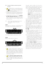
Tab. 4 specifies the physical connection between the UPS
and the battery module or modules.
Model
Batteries
(U
element
x No.) =
U
rated
/ U
float
Two-pole switch
Voltage
DC (V) Current (A)
SLC-6000-TWIN PRO2 T UL
(12 V x 20) =
240 V / 275 V
440
32
SLC-10000-TWIN PRO2 T UL
50
Tab. 2.
Characteristics of the protection to be installed in
user-owned battery modules.
•
All standard UPSs incorporate the batteries in the same
cabinet as the device, except the B1s. In all of them, bat-
tery protection is by means of internal fuses and is not ac-
cessible to the user.
Accumulator enclosures or modules also have battery pro-
tections and in this case in duplicate. A number of internal
ones with fuses not accessible to the user and other two-
pole ones with circuit breaker or disconnector with acces-
sible fuses for this one.
•
IMPORTANT FOR SAFETY: If batteries are installed
independently, the accumulator bank must be fitted
with fuses or a two-pole circuit breaker with the character-
istics indicated in Tab. 3.
•
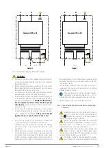
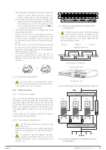
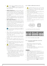
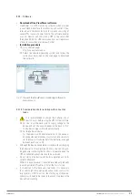
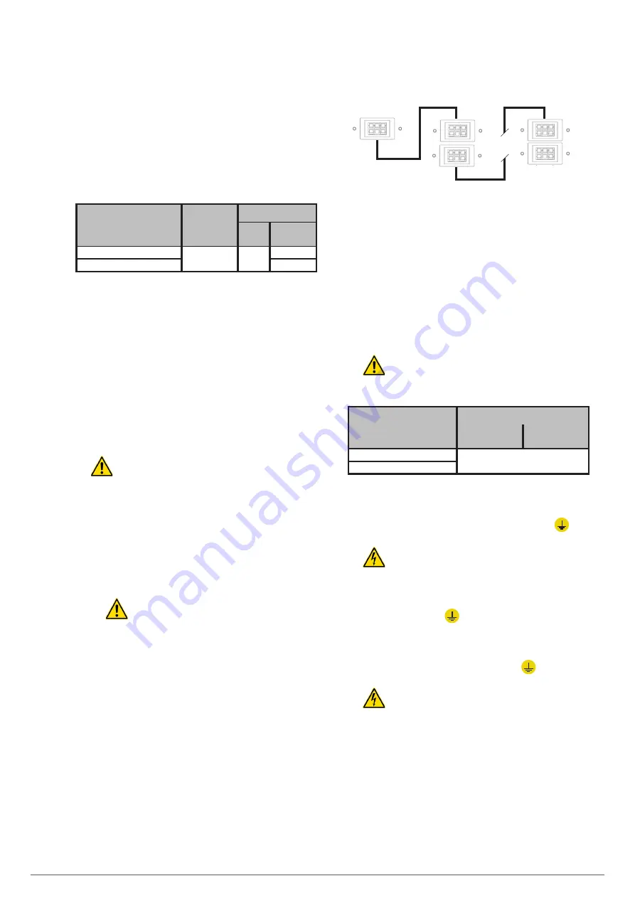
The connection of the UPS to the battery module must be
made using the supplied cable hose, first connecting one
end to the terminals or connector of the UPS and the other
to the terminals or connector of the battery module. As an
example, see Fig. 16.
In the case of connectors, there is no possibility of error
as they are of the polarised type.
For connection to terminals, respect the polarity
indicated on the labelling of each element and
in this manual, and the colour of the cables (red for
positive, black for negative and green-yellow for earth).
•
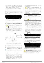
When more than one battery module is supplied for each
UPS, the connection between them and it will be in parallel.
• • •
Connector on the
back of the UPS
Connectors on the back of the
battery modules
Battery
module 1
Battery
module
‘
n
’
Fig. 15.
Example of connection between UPS and battery
modules, through connectors.
•
All battery modules have two connectors or groups of
terminals to simplify connection to the UPS and other
modules in parallel, in extended backups.
•
In models with terminals, always respect the established
colour and polarity cable convention (positive red and
negative black).
•
Each battery module is independent for each device.
It is strictly forbidden to connect two devices
to the same battery module
.
Model
Connection mode with batteries
In the UPS
In external
battery module
SLC-6000-TWIN PRO2 T UL
Connector
SLC-10000-TWIN PRO2 T UL
Tab. 3.
Connection mode between UPS and battery modules.
5.2.4. Connection of the earth bonding terminal
.
•
As it is a device with protection against class I elec-
trical shock, it is essential to install the protective
earth cable. Connect this conductor to the terminal before
supplying voltage to the input terminals.
•
Make sure that all of the loads connected to the UPS are
only connected to its
earth bonding terminal. Failure to
limit the earthing of the load or loads and battery module or
modules to this
single point
will create earth return loops
that will degrade the quality of the power supplied.
•
All terminals identified as earth bonding
are linked to-
gether and to the earth of the device.
•
Never under any circumstances disconnect the
earth cable from the building and/or the UPS.
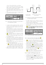
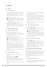
5.2.5. Terminals for EPO (emergency power off).
•
The UPSs have two terminals for the installation of an ex-
ternal emergency power off
(EPO)
output button.
•
The device is dispatched from the factory with its EPO cir-
cuit set to closed
(NC)
by default. In other words, the UPS
will cut the output power supply, emergency power off,
when the circuit is opened:


