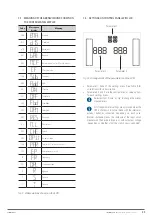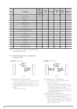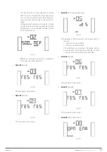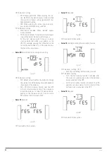
21
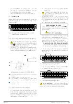
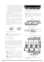
Either by removing the female connector from the socket
where it is inserted. This connector has a cable con-
nected as a jumper that closes the circuit [see Fig. 17-A].
Or by pressing the button external to the device be-
longing to the user installed between the terminals of
the connector [see Fig. 17-B]. The connection on the
button must be in the normally closed contact
(NC)
, so
it will open the circuit when activated.
•
The opposite functionality can be selected through the
communications software.
Except for specific cases, we advise against this type of
connection in view of the purpose of the EPO button, since
it will not act upon an emergency request if either of the
two cables that run from the button to the UPS are discon-
nected.
By contrast, this anomaly would immediately be detected
in a closed EPO circuit, with the inconvenience of an unex-
pected cut in the powering of the loads, but a guarantee of
effective emergency functionality.
•
To recover the normal operating state of the UPS, it is
necessary to insert the connector with the jumper in its re-
ceptacle or deactivate the EPO button. The device will be
operational.
A
B
Fig. 16.
Connector for external EPO.
•
Fig. 17-A: In the case of a parallel system, individual
contacts must be used. Do not join the EPO contacts
with each other under any circumstances.
5.2.6. Parallel connection.
5.2.6.1. Introduction in redundancy.
N+X is usually the most reliable power structure. N represents
the minimum number of devices that the total load needs; X rep-
resents the number of redundant devices, that is, the number
of faulty UPSs that the system can simultaneously allow. The
higher X is, the greater the reliability of the system. For occa-
sions where reliability is essential, N+X will be the optimum
mode.
Up to 3 devices can be connected in parallel to configure a
shared output and power redundancy.
5.2.6.2. Installation and parallel operation.
•
The COM communications line is a very low voltage
safety circuit.
To preserve the quality, it must be installed separately from
other lines carrying dangerous voltages (power distribution
line).
•
Pay attention to the ‘Recommended installation’
documentation mentioned in section 5.1.5.4., which
specifies cable sections, sizes and characteristics of the
protections, etc.
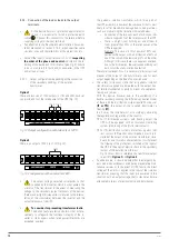
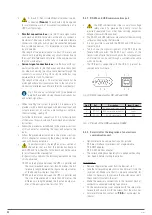
A
N
0
208V
240V
Non-In
L
N
L2
OUTPUT
ISO TAP SELECTION
INPUT
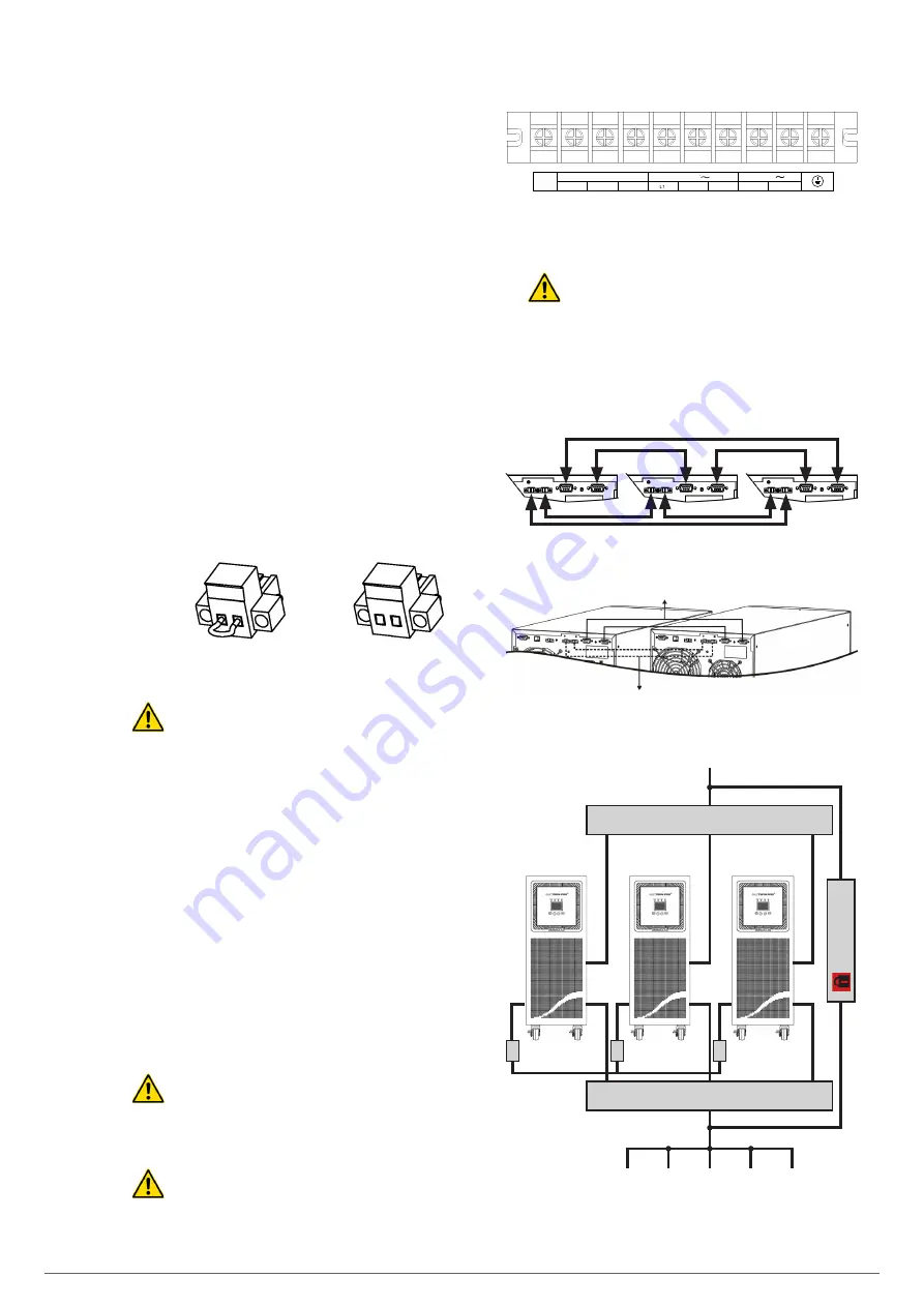
Fig. 17.
Physical arrangement of the terminals of the
terminal block
•
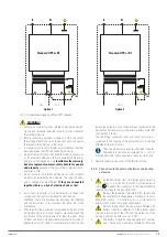
The Non-In terminals of each of the UPSs that make
up the parallel system must be connected to each
other. If this connection is not made, the UPSs will fail be-
cause this terminal acts as an internal reference for the
devices connected in parallel.
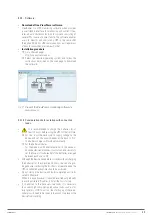
Parallel connection bus
Current signal connection bus
UPS no. 1
UPS no. 3
UPS no. 2
Communications bus
Current signal bus
Fig. 18.
Communication and current signal bus connection.
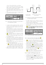
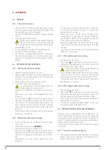
Input circuit breaker
Output circuit breaker
Manual bypass
UPS no. 1
A
C
B
UPS no. 2
UPS no. 3
Input
To loads
Fig. 19.
Parallel installation of a distribution board with
manual bypass.
SLC TWIN PRO2 T
UL
UNINTERRUPTIBLE POWER SUPPLIES (UPS)
USER MANUAL


