22
SALICRU
•
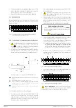
A, B and C: Non-isolated Neutral terminal line dis-
connectors
(Non-in)
. They should only be opened
for maintenance work or disconnection/connection of a
UPS from the system.
•
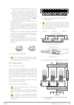
Parallel connection bus
. Use the 15-wire signal cable
with mesh and DB15 connectors at the ends to connect a
maximum of 3 devices. Each hose has a male and a female
connector at the ends, which must be connected between
two correlative devices. It is imperative to close the bus
loop in parallel.
The length of the parallel cable is about 1.5 meters and
should not be prolonged under any circumstances due to
the risk of interferences and failures in the communication
that this would entail.
•
Current signal connection bus
. Use the hose with con-
nectors at the ends to join the devices and close the current
bus when connecting two consecutive devices through the
connectors, as shown in Fig. 18. Lastly, close the bus loop
between the last and first devices.
The length of the cable is 1.5 metres and should not be
prolonged under any circumstances due to the risk of com-
munication interference and failure that this would entail.
Fig. 18 shows an installation with three devices in
parallel. Proceed by closing the communications bus
and current signal bus.
•
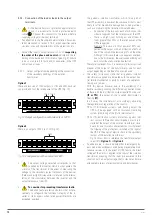
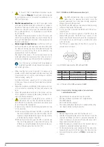
When installing the system in parallel, it is necessary to
provide it with a board equipped with individual input and
output protections, as well as a manual bypass with me-
chanical locking, see Fig. 19.
For further information, see section 5.1.5.4. for descriptions
of the manual bypass board and ‘Recommended installation’
instructions.
•
Follow the procedures established in the previous sections
of this chapter for connecting the input and output to the
loads.
•
Follow the procedure established in the previous sections
of this chapter for connecting the battery modules of de-
vices with backup extension.
•
In parallel systems, the length and cross section of
the cables that run from the distribution board to
each UPS and from the UPSs to the board will be the same
for all of them without exception.
In the worst of conditions, the following deviations must be
strictly observed:
When the distance between the UPSs in parallel and
the circuit breaker board is less than 20 metres, the dif-
ference in length between the input and output cables
of the device must be less than 20%.
When the distance between the UPSs in parallel and
the circuit breaker board is more than 20 metres, the
difference in length between the input and output ca-
bles of the device must be less than 10%.
5.2.7. RS-232 and USB communications port
•
The COM communications line is a very low voltage
safety circuit. To preserve the quality, it must be
installed separately from other lines carrying dangerous
voltages (power distribution line).
•
The RS-232 and USB interfaces are useful for the monitoring
software and updating the firmware.
•
It is not possible to use both the RS-232 and USB ports at
the same time.
•
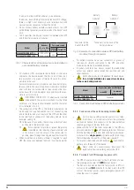
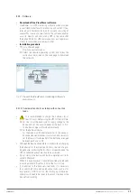
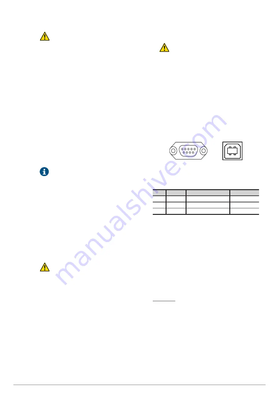
Tab. 4 shows the signal assignment of the RS-232 in the
female DB9 connector. The RS-232 port consists of the
transmission of serial data in such a way that a large amount
of information can be sent through a communication cable
with only 3 wires.
•
The USB port is compatible with the USB 1.1 protocol for
communication software.
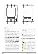
5 1
9 6
2 1
3 4
Fig. 20.
DB9 connectors for RS-232 and USB.
Pin #
Ref.
Description
Input / Output
2
RS-232
TXD (serial data transmission)
Output
3
RS-232
RXD (serial data reception)
Input
5
RS-232
RS-232 signal earth
GND
Tab. 4.
Pinout of the DB9 connector, RS232.
5.2.8. Smart slot for the integration of an electronic
communication unit.
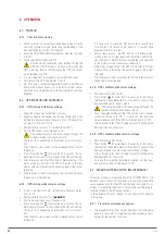
•
Optional electronic communication units include:
Relay interface to terminals, not programmable.
SNMP adapter.
RS-485 modbus adapter.
•
The corresponding documentation is supplied with each op-
tion. Read it before starting installation.
Installation.
•
Remove the protective cover from the device’s slot.
•
Take the corresponding electronic unit and insert it into the
reserved slot. Make sure that it is properly connected, for
which it is necessary to overcome the resistance caused in
the connector located in the slot.
•
Make the necessary connections in the terminal block or
connectors available according to each case.
•
Fit the new protective cover supplied with the relay inter-
face card and secure it with the screws from the old cover.
•
For more information, contact our
T.S.S.
or our nearest dis-
tributor.


