29
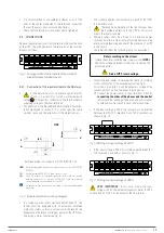
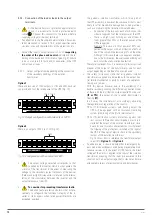
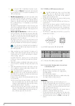
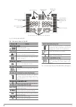
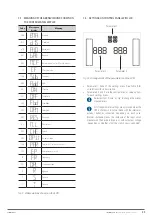
7.3. MEANING OF THE ABBREVIATIONS SHOWN ON
THE CONTROL PANEL DISPLAY.
Code
Message on
display
Meaning
ENA
A
U
E
Enabled.
DIS
d1S
Disabled.
ATO
AtO
Automatic.
BAT
bAt
Battery.
NCF
CF
U
Normal mode (not for CF work mode).
CF
CF
CF work mode.
SUB
SUb
Subtract.
ADD
Add
Add.
ON
ON
Startup.
OFF
OFF
Shutdown.
FBD
Fbd
Forbidden.
OPN
OP
U
Permitted.
RES
RES
Reserved.
N.L
U
.
L
Neutral loss.
CHE
CHE
Check.
OP.V
OP
.
U
Output voltage
PAR
PAR
Parallel, 001 refers to the first.
EPO
EP
Emergency power off.
FR
FR
Frequency.
OPL
OPL
Load percentage.
R
R
R phase.
S
S
S phase.
T
T
T phase.
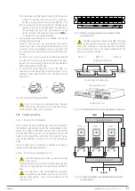
Tab. 9.
Abbreviations shown on the LCD.
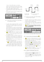
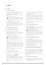
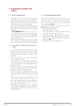
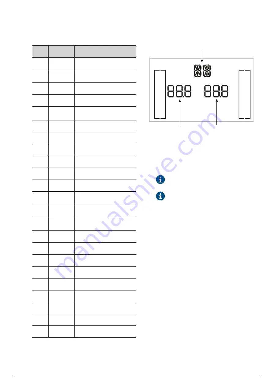
7.4. SETTINGS ON CONTROL PANEL WITH LCD.
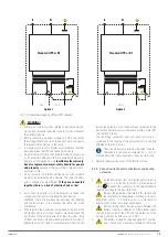
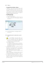
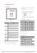
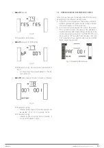
Parameter 1
Parameter 2
Parameter 3
Fig. 24.
Arrangement of the parameters on the LCD.
•
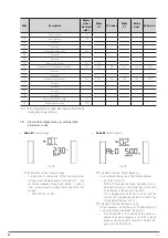
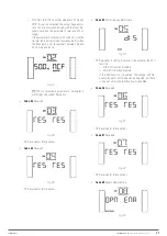
Parameter 1: Code of the settings menu. See Table 9 for
correlation with its descriptive.
•
Parameters 2 and 3 are the configuration or value options
for each settings menu.
Select buttons
‘
Down
’
or
‘
Up
’
to change the menus
or parameters.
All of the parameter settings are only saved when the
UPS is shut down in normal mode with the internal or
external batteries connected, depending on each case.
(Normal shutdown means the shutdown of the input circuit
breaker with the device in bypass or without output voltage
- depending on whether or not the static bypass is enabled).
SLC TWIN PRO2 T
UL
UNINTERRUPTIBLE POWER SUPPLIES (UPS)
USER MANUAL


