33
•
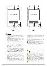
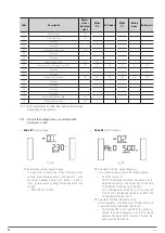
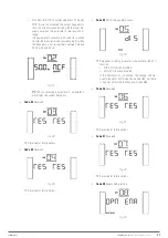
Code 14
Reserved.
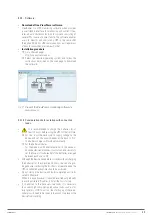
Fig. 39.
Reserved for future options.
•
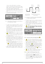
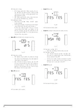
Code 17
External BATT MOD setting.
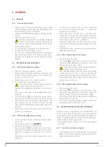
Fig. 40.
Parameter 3 setting: Sets the number of external BATT
MOD.
–
0-7: the setting allows values between 0-7. The de-
fault setting is 0.
•
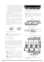
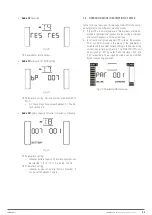
Code 18
Battery capacity for correct calculation of backup.
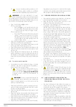
Fig. 41.
Parameter 2 setting:
–
Indicates battery capacity. The following values can
be selected: 7, 9, 10, 12, 17, 26, 40, 65, 100 Ah.
Parameter 3 setting:
–
Indicates number of parallel battery branches. It
can be set to between 1 and 6.
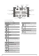
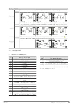
7.5. OPERATING MODE / DESCRIPTION OF STATE.
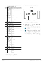
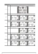
Table 10 shows the screens displayed on the LCD of the control
panel [state] for the different operating modes.
1.
If the UPS is in normal operation, three screens will be dis-
played to represent the input and output voltage, the input
and output frequency, and the output load.
2.
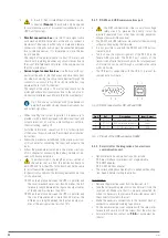
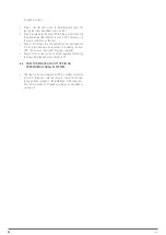
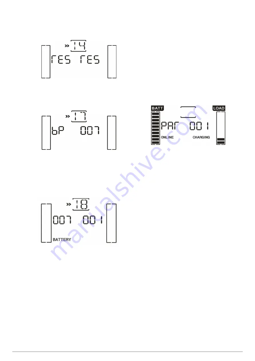
In correctly configured parallel UPS systems, the acronym
‘PAR
’
will be displayed in the place of the parameter 2
variable and the number corresponding to the device of the
system in parallel in parameter 3. The ‘MASTER
’
UPSs will
be assigned as ‘001
’
by default and the slaves ‘002
’
and
‘003
’
respectively. The assigned numbers can be modified
dynamically during operation.
Fig. 42.
Parallel system screen.
SLC TWIN PRO2 T
UL
UNINTERRUPTIBLE POWER SUPPLIES (UPS)
USER MANUAL

