


VHF 5000 System
Functional unit workshop service
3-37
Reference
Operation/Test
Test Criteria
Comments/instructions
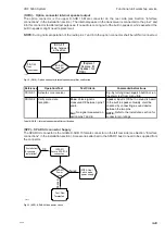
MKDC-01 Power up radio
Pass:
All power supplies are
measured within
See Figure (ref XX). Voltages are
Fail:
Otherwise
“LIGHT” connector:
• Pin 5: +12.5V
“DISPLAY” connector:
• Pin 1: +5V
• Pin 19: +3.3V
Pass:
Display switches to
power off countdown when
on/off is pushed.
Fail:
No reaction if on/off is
pushed
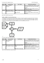
Pass1:
Keyboard light is
activated all over the key
pad.
1)
Adjust the dimming level to maximum.
If keyboard light is not activated at all the
problem can also be in cable or baseband
board.
Pass2:
All segments are
activated.
2)
Run LED test from the self-test menu
(5.3).
Fail:
Otherwise.
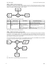
Pass1:
Display has
adjustable backlight.
1)
Adjust the dimming level to maximum.
If display back light is not activated at all,
the problem can be in cable or baseband
board.
Pass2:
Pattern is perfectly
recognized without any
missing pixels or areas.
2)
Run Display test from the self-test
menu (5.2).
Fail:
Otherwise
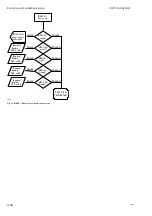
Pass1:
Volume and squelch
knobs can control the
volume and squelch indicator
1)
Turn knobs left and right.
Pass2:
Keypad test passed.
2)
Run Key test from the self-test menu
(5.1)
.
Fail:
Otherwise
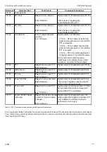
MKDC-06 Verify keypad and controls
MKDC-04 Verify keyboard light and
upper display segment
light
MKDC-05 Verify graphical display
MKDC-02 Power supply check
MKDC-03 Power on/off
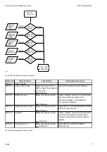
Tabel 17 (MKDC) - Radio front module checks
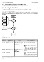
(MPC) – Module power connections
Three cables are connecting the main power supply:
0608
Summary of Contents for RT5022
Page 2: ......
Page 4: ...VHF 5000 System 0930 ...
Page 16: ...Maintenance VHF 5000 System 2 2 ...
Page 70: ...Feature sales VHF 5000 System 4 2 ...
Page 82: ...Installation VHF 5000 System 5 12 0608 ...
Page 83: ...VHF 5000 System Installation 5 13 0608 ...
Page 84: ......


