


VHF 5000 System
Functional unit workshop service
3-23
3.2.15
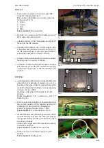
Detailed fault finding
Identifying failures on the external connectors
This section will describe some possible scenarios to follow if the RT5022/RT5020 seems to be working poor
or not at all together with attached external devices.
Before dismantling the transceiver unit, check always first the installation (with reference to the installation
section in the manual). A full replacement of the RT5022 or RT5020 transceiver, to verify the installation, might
save time before looking for errors inside the transceiver.
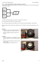
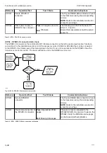
(PC) - Power connector
If you reach this section of the manual, it is because it has been impossible to power on the product. Installations
and battery is already checked and found OK. The power connector is located on the rear side top right (see
Section “Interface connections” in the installation section).
(PC-01)
Replace supply
fuse
(PC-02)
Startup?
(Replace)
replace
power
connector
Test Flow
Terminated
Failed
40423
(Installation)
battery and
cable check
(PC-03)
Check power
connector
(PC-02)
Startup?
Failed
(PC-02)
Startup?
(SMPS-flow)
Switch mode
power
supply
OK
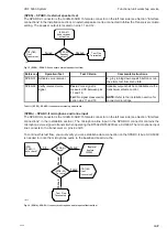
(PC-01)
Replace supply
fuse
(PC-02)
Startup?
(Replace)
replace
power
connector
Test Flow
Terminated
Failed
40423
(Installation)
battery and
cable check
(PC-03)
Check power
connector
(PC-02)
Startup?
Failed
(PC-02)
Startup?
(SMPS-flow)
Switch mode
power
supply
OK
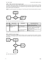
Fig. 6 (PC) - Power connector validation flow
Reference
Operation/Test
Test Criteria
Comments/instructions
PC-01
Replace main fuse in
power line
On the back of the radio the main fuse is
located. Check the fuse is fixed or replace
the fuse with another one. See also
installation section of the RT5022/RT5020
Pass:
The radio can be
powered, and it is possible –
without warning messages to
transmit with 25W output.
Fail:
Otherwise
Check the sanity of the power connector.
Pull out power cable and check for
corrosion. If OK insert again and secure
Power connector should be replaced if in
bad condition.
PC-02
Check start-up of
product.
Verification should be done with mounted
antenna on the RX/Tx antenna output, or
dummy load.
PC-03
Check power connector.
Tabel 2 (PC) - Power connector test operations
0608
Summary of Contents for RT5022
Page 2: ......
Page 4: ...VHF 5000 System 0930 ...
Page 16: ...Maintenance VHF 5000 System 2 2 ...
Page 70: ...Feature sales VHF 5000 System 4 2 ...
Page 82: ...Installation VHF 5000 System 5 12 0608 ...
Page 83: ...VHF 5000 System Installation 5 13 0608 ...
Page 84: ......


