background image

VHF 5000 System

Functional unit workshop service

3-1

0608

3

Functional unit workshop service

This chapter will explain in detail for each system component:

The service concept

How to replace parts that are covered by this service concept

Verification of the unit that has been repaired

Repairs and components that are not covered by the service concept will not be supported or supplied by Thrane
& Thrane.

3.1

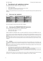
Necessary test equipment

Function

Recommended type

Parameter

Multi meter

Fluke

R; >100K ohm

Oscilloscope Textronics

400MHz

Power meter 

Bird

50W

Frequency counter

Agilent

Solution 1Hz

Signal Generator

Agilent

150-170MHz

Dummy load ohm 

Bird

50ohm 50W

Also recommended to use radio test set like CMT or Stabilock

3.2

Servicing the RT5022/RT5020 VHF transceiver

The VHF transceivers functionally exist in the following variants:

RT5022 VHF DSC Simplex, semi-duplex

RT5020 VHF DSC Duplex

Software updates and configuration tasks can always be performed on board using the SB5006 service tool.

Simple repairs, where the product is disassembled, and larger modules are exchanged, e.g. base unit or front
unit, can also be performed on board, followed by a simple interface check performed from the transceiver user
interface.
More detailed repairs inside the transceiver require the use of instruments to validate performance after repair.
It is up to the service technician to decide whether the repair should be performed on board the ship or in the
workshop.

3.2.1

Software

The software file always covers all functional transceiver models. The product difference is in the hardware, and
which parts of the software that are enabled. The SB5006 is used to configure the software for the specific radio
type.
We strongly recommend the products being updated with the newest software available. A few minutes should
be spent to consider the following:

All software parts are physically stored on the Base Band module.

If the product is damaged in a way that no contact can be established to the Base Band module via the
SB5006 service tool, all configuration data might be considered as lost for that radio.

If it is possible to save configuration data before a possible Base Band module exchange, this should be
done via the SB5006 service tool.

Updating the VHF transceiver to a new software version does not affect configuration data (contact list, private
channels, etc.). Configuration data should always be compatible with new software releases.

Summary of Contents for RT5022

Page 1: ... System Workshop Manual For a complete workshop manual for VHF 5000 System includes the following manuals B5006COM Operation Manual SB5006 Service Tool B5022GB0 Operation Manual RT5022 VHF RT5020 VHF DSC Duplex ...

Page 2: ......

Page 3: ...tailed operations of the separate units But the interconnections medias protocols supplies antennas etc are described Disclaimer Any responsibility or liability for loss or damage in connection with the use of this product and the accompanying documentation is disclaimed by Thrane Thrane The information in this manual is provided for information purposes only is subject to change without notice an...

Page 4: ...VHF 5000 System 0930 ...

Page 5: ... 3 2 11 Removing installing the BB module from the VHF transceiver unit 3 16 3 2 12 Removing installing the RF module of the VHF transceiver unit 3 18 3 2 13 Removing installing the PA module of the VHF transceiver unit 3 20 3 2 14 Removing installing the internal loudspeaker of the VHF 3 22 3 2 15 Detailed fault finding 3 23 3 3 Servicing the HS5001 transceiver handset 3 42 3 3 1 Manuals 3 42 3 3...

Page 6: ...box and 2 x extension box 5 7 5 2 Special installations 5 8 5 2 1 Flush mounting with Retrofit 5 8 5 2 2 Installing the Oki Microline Printer 5 8 5 2 3 Installing other printers 5 8 5 2 4 Acquiring a printer server 5 8 5 2 5 Connecting the LB5007 LAN box 5 11 5 2 6 Multiple unit equipment 5 11 5 2 7 External speakers for the transceiver or remote CU positions 5 11 1007 ...

Page 7: ... Handset Rx Tx Antenna DSC Antenna Option The VHF radio is a transceiver which means it consists of a transmitter and a receiver The radio has four main blocks SMPS Built in Switch Mode Power Supply which converts the input battery voltage to internal supplies for the radio It also separates the battery potential from the radio MKD Keyboard and Display unit All controls and indicators are placed o...

Page 8: ...2 Mixer IF AMP Ceramic filters Limiter 450KHz Filter 45 MHz IF1 AMP IF1 lexer Dip Mix First BP LNA BP LO1 201 025 207 025 MHz Buffer VCO PLL 44 55MHz Tripler LO2 44 55 MHz Synth Control RX Lock Det TCXO 14 85MHz VCO PLL Buffer Dubler 29 7MHz 29 7MHz LO2 1LO 126 375 MHz DSC Antenna BP LNA BP First Mix 3dB Att IF1 AMP IF1Filter 30 15MHz 2 IF System IC 2 Mixer IF AMP Ceramic filters Limiter 450KHz DS...

Page 9: ...locking immunity The IF section is with no adjustable coils In fact the receiver has no adjustment at all The 2nd mixer and 2nd IF section ensures good selectivity The IF frequency of 450 kHz is filtered and demodulated to AF signal which is led to the Base Band for further handling Synthesizers There are three synthesizer sections One for each receiver and one for the transmitter The synthesizers...

Page 10: ...C Transmitter Synth Control Tx Control SPI MCBSP SPI UART SPI CODEC DSP Ant Relay Rx Tx Shift VHF Receiver SPI Power Detect DSC Receiver Synth Control SPI Synth Control Flash Memory SRAM Memory Temp RTC SPI UART S MCU Options SPARC MCBSP Speaker Internal Handset RS485 SDRAM Super cap Alarm LAN MIC CU Earpice Control Speaker GPS VDR MIC Earpice Handset Ptt Hook on off AUX 1 2 DSC call DSC alarm NME...

Page 11: ...rambling of voice signals from the microphone During transmission of DSC and ATIS messages the DSP carries out the FSK modulation The modulation indexes related to the different modulation signals are adjusted internally in the DSP Front Control Unit The MKD module is connected to the baseband board through 4 interfaces determined for sending keyboard data receiving display data controlling keyboa...

Page 12: ...criptions Relays in option connector Alarm outputs OPTION plug Pin 3 AUX2 Pin 4 AUX2 NO Base Band Pin 5 AUX1 Pin 6 AUX1 NO 12 5V 12 5V 12 5V 12 5V Pin 9 DSC Call Pin 10 DSC Call NO Pin 14 DSC Alarm Pin 15 DSC Alarm NO AUX2 AUX1 DSC Call DSC Alarm CPU Network 40363 GPS NMEA input NMEA interface OPTION plug Pin 12 NMEA Pin 13 NMEA Base Band 40364 0608 ...

Page 13: ...housing In the housing is also placed a reed switch and together with a strong magnet in the cradle it forms a hook off function The handset used together with the remote control unit CU5000 is waterproof 1 3 The CU5000 remote control unit Should also include short description of the handset used 40341 Sparc II to External Laudspeaker DISPLAY CPU KEYBOARD RS 485 Att 2 Att 1 Audio PA Int Loudspeake...

Page 14: ...V to 5V and 3 3V converter Sub D Ethernet to PC 40368 Principle of operation LAN Service box The unit converts the data from the Sparcbus to Ethernet data The same unit is used for two applications The LAN box is for fixed installation for connection to a printer and or a PC The service box is the same unit but only used by service personal for configuration and service purpose of the VHF 0608 ...

Page 15: ...ftware updates A service message will be sent when new software files are available for download from the extranet The newest software file shall be downloaded on the service PC We recommend the newest software available always be updated on equipment that runs an older software version This will assure the maximum exploitation of the VHF 5000 equipment The distributed software will always be cert...

Page 16: ...Maintenance VHF 5000 System 2 2 ...

Page 17: ...be performed on board followed by a simple interface check performed from the transceiver user interface More detailed repairs inside the transceiver require the use of instruments to validate performance after repair It is up to the service technician to decide whether the repair should be performed on board the ship or in the workshop 3 2 1 Software The software file always covers all functional...

Page 18: ... running the service tool Connect SB5006 service tool Pass Otherwise HTML file system missing in VHF radio Please download new software SB5006 configured wrong Configure to auto negotiate Fail Error messages after any start up attempt Pass No error messages after start up SW 05 Fix normal errors Start up errors like missing serial number or missing MMSI number should be fixed according to the desc...

Page 19: ...ce and to some extend the often limited time available onboard to perform the repair Onboard service repair The onboard service repair besides the VHF equipment itself encompasses also the part of the ship s installation pertaining to the operation and performance of the VHF equipment i e antenna installations associated cabling ships power supply external power supply units etc all of which must ...

Page 20: ...w 1 Row 2 Row 3 Row 4 Volume 2 Volume 1 Squelsh 1 Segment latch 1 Segment latch 2 Indicator latch Volume latch Squelsh latch NOT IN USE Squelsh 2 DISPLAY Pin 1 2 3 4 5 6 7 8 9 10 11 12 13 14 15 16 17 18 19 20 Description 5V Ground Not in use Data 0 Data 1 Data 2 Data 3 Data 4 Data 5 Data 6 Data 7 Chip select 1 Display reset Ground DI Display write Ground 3 3 V Backlight Chip select 2 Pin 1 2 Descr...

Page 21: ...VHF 5000 System Functional unit workshop service 3 5 1007 3 2 6 Available spare parts Check eShop at http extranet thrane com ...

Page 22: ...as been installed using the Mounting Bracket remove the two Mounting Plates item 3 by removing the 6 x Screw M4x8 item 4 Tools required Torx screwdriver size 15 Remove the 4 x Screws M3x8 with Washers items 1 and 2 Tools required Torx screwdriver size 10 The cover item 5 can now be removed by pulling it backwards from the Radio 1 2 3 4 5 40161A ...

Page 23: ...t Removal Installing Remove 4 x Screw M2 5x8 item 8 Tools required Torx screwdriver size 8 The base control unit item 7 can now be disassembled from the base unit item 6 by pulling forwards Remove 3 x ribbon cable and loudspeaker cable between base control unit item7 and base unit item6 5 6 7 8 40162A 5 7 8 6 12 9 10 11 ...

Page 24: ...toremove install the Duplex Filter The sequence of the proce dures applicable to the removal and the installation respectively is consecutively numbered 1 through 3 and should be carried out in accordance with this Removal Remove 4 x Cables on the bottom of the radio See Fig 1 Tools required Flat nose pliers Remove 4 x Screw M3x8 The duplex filter including bracket can now be removed from the radi...

Page 25: ...KDC flow MKD power MPC Flow Module power Fig 2 SMPS module replacement See section 3 2 15 for details on fault identification No other fault identification tests are available before replacement of this module Use the following procedures illustrations to remove install the SMPS The sequence of the procedures applicable to the removal and the installation respectively is consecutively numbered 1 t...

Page 26: ...two 2 screws Torx TX10 see Fig 4 securing the cover to the PSU chassis and carefully lift the cover from the PSU Retain screw and cover for re installation later Remove the four 4 TORX TX10 screws located inside the PSU at the base the two 2 stand offs and two 2 TORX TX10 screws located at the rear side of the radio securing the E shaped cooling profile to the radio chassis Remove the two 2 20 pin...

Page 27: ...regulator transistors against the E profile and remove the E profile from the PSU module Retain the E profile for use with the replacement PSU module Retainer clips may be discarded of as new clipsareincludedwiththereplacementPSUmodule Prepare the new PSU module by soldering the DC power plug supplied with the replacement module to the PCU PC board Refer to the removed PSU for correct wiring Fig 6...

Page 28: ...PSU module in the chassis Install the screws and the two 2 stand offs which were removed in step 4 Note When tightening up the screws and stand offs exercise care not to over tighten to avoid damaging the threads in the chassis Verify that the two insulation sheets at the E profile are in good condition If damaged in any way they should be replaced Fig 10 Fig 11 Fig 12 Fig 13 ...

Page 29: ... module 1007 Install the Prespan carbon sheet between coil and the E profile to ensure insulation of the coil from chassis Carefully install a retainer clip over each of the regulator transistors to hold these tight against the E profile to ensure proper cooling Using a piece of cardboard of approx 1mm thickness check and ensure sufficient spacing of clips to surrounding components to avoid clips ...

Page 30: ...off 1007 Use a small amount of sealing compound must not contain acid to provide support of the ferrite coil and power plug wiring to the E profile Reinstall the cover on top of the PSU module and secure it using the two 2 screws Position the DC power plug in the rear chassis of the radio and secure it using the two 2 socket screws Fig 18 Fig 19 Fig 20 Fig 21 ...

Page 31: ... using a small amount of sealing compound must not contain acid Connect the two 2 20 pin ribbon cable connectors to the RF board and the Baseband board respectively Connect the front part Control Unit to the radio Assemble the cover of the radio and perform a final test of the complete radio 1007 Fig 22 Fig 23 Fig 24 ...

Page 32: ...er control TIAF flow transceiver Replace replace baseband TIC flow audio SW Flow Software flow OCGP Flow option connect GPS OCVDR flow option VDR option conn relay SPD flow SPARC II OCR flow data 40462 HSC Flow Handset connector MKDC flow Radio front conn MPC Flow module power tranceiver control TIAF flow transceiver Replace replace baseband TIC flow audio SW Flow Software flow OCGP Flow option co...

Page 33: ...n opposite corners of the BB module securing this to the chassis Carefully lift out the BB module from the chassis position the BB module correctly in the transceiver chassis Secure by installing two screws in opposite corners of the BB module applying a torque of max 0 7Nm Installretainingplateontopofaudiopoweramplifier ICandsecurethisagainsttheheatsinkbytightening 2 x screws applying a torque of...

Page 34: ... contact list etc before base unit Base Band module is replaced After the repair has been done any saved configuration parameters can be copied back to the radio NOTE The System Parameters e g serial number are not part of the configuration parameters that can be automatically copied 3 2 12 Removing installing the RF module of the VHF transceiver unit 40463 Replace replace PCB or PA MPC Flow modul...

Page 35: ...t the RF module while being careful not to bend pins of the PA module in the process Installing carefully position RF module in chassis while being observant not to damage or cause e x c e s s i v e bending of the pins of the PA module Secure RF moduletochassisbyinstalling 4xscrews applying a torque of max 1 0Nm Carefully solder pins of PA module to the RF module Tools required Torx screwdriver si...

Page 36: ...ppropriatecablegrooveoftheRFmoduleshielding cover Removal Disconnect 4 x cables connecting duplex filter to the RF module See Fig 1 Each cable is identified by a coloured sleeve as follows See Fig 2 1 Green 2 Yellow 3 Red 4 Blue Tools required Flat nose pliers Remove 10 x screws securing shielding cover of RF module and remove cover Unsolder the pins of the PA module and lift these from the RF mod...

Page 37: ...st the pc board and against the grounding strip heatsink Tighten the 4 screws in the sequence indicated by the numbering applying a torque of max 0 7N Insert glasflex insolation over each PA module pin Solder each pin to the RF module soldering pads Tools required Soldering iron Position the shielding cover correctly over the RF module Install all 10 x screws loosely followed by tight ening the ou...

Page 38: ...tification No other tests have been created for further verification Use the following procedures illustrations to remove install the internal loudspeaker of the VHF5000 Note The Base Control Unit should be detached from the VHF Base Unit before proceeding refer to para 3 2 5 Fig 1 Fig 2 Removal Remove 4 x screws securing the loudspeaker and loudspeaker housing to the Base Control Unit Remove loud...

Page 39: ...0423 Installation battery and cable check PC 03 Check power connector PC 02 Startup Failed PC 02 Startup SMPS flow Switch mode power supply OK PC 01 Replace supply fuse PC 02 Startup Replace replace power connector Test Flow Terminated Failed 40423 Installation battery and cable check PC 03 Check power connector PC 02 Startup Failed PC 02 Startup SMPS flow Switch mode power supply OK Fig 6 PC Powe...

Page 40: ...een checked OK as well RTA 01 secure antenna connector screw RTA 02 RF fail 40425 Installation Aerials and cable check Test Flow Terminated Passed OK RTA 03 Reports RTA 04 DSC test RTA 05 DSC test Replace Replace PA power amplifier Failed Failed Failed Failed RF flow Fault finding RF module or PA Passed Passed Passed RTA 01 secure antenna connector screw RTA 02 RF fail 40425 Installation Aerials a...

Page 41: ...in the display but the product seems otherwise functional proceed to PA replacement During Rx Tx shifts PTT no error messages with the category System malfunction must be shown e g Synthesizer lock errors RTA 03 Check reports for other errors in transceiver display RTA 04 Make a DSC test RTA 05 Check output power RTA 02 Check reports for severe RF module errors in transceiver display Tabel 3 RTA R...

Page 42: ...tion OCGP 03 Self test Replace Replace BB base band board Test Flow Terminated Installation GPS unit and cables Passed Passed Failed OK Failed Fig 9 OCGP Option connector GPS tests Reference Operation Test Test Criteria Comments instructions The 15 pole DSUB cable connector is fixed to the transceiver using the NOTE Refer to the installation section for connector pin ratings Pass The header line m...

Page 43: ...OCVDR 03 Transmit Replace Replace BB base band board Test Flow Terminated 40431 Installation VDR unit and cables Passed Passed OK Failed TIC TIAF flow Transceiver Failed Fig 10 OCVDR Option connector VDR test flow Reference Operation Test Test Criteria Comments instructions The 15 pole DSUB cable connector is fixed NOTE Refer to the installation section for connector pin ratings Pass Voice signal ...

Page 44: ...se band board Test Flow Terminated 40431 Installation external unit and cables Passed OK Failed OCR 02 Initial state Fig 11 OCR Option connector relay test flow Reference Operation Test Test Criteria Comments instructions The 15 pole DSUB cable connector is fixed to the transceiver using the corresponding screws NOTE Refer to the installation section for connector pin ratings The DSC CALL and DSC ...

Page 45: ...tions OCIS 01 Activate voice receiver E g by turning down squelch button or run the alarm test from menu 5 4 Pass Voice signal is measured OK between pins 7 and 8 Speaker input is OK but no sound is heard in the built in speaker Quality could be checked by connecting a sound device between the two pins Fail No signal measured on option pins 7 and 8 NOTE Refer to the installation section for connec...

Page 46: ...RC II bus the transceiver connection is OK The best verification unit is the SB5006 service tool SPP 01 Secure SPARC II connector SPD 01 Data conn Replace Replace BB base band board Test Flow Terminated SW flow Software updated 40421 Installation Accessory installation OK OK Failed Passed check SPP 01 Secure SPARC II connector SPD 01 Data conn Replace Replace BB base band board Test Flow Terminate...

Page 47: ...easured on option pins 11 and 12 NOTE Refer to the installation section for connector pin ratings SPES 02 Verify received voice signal Tabel 11 SPES SPARC II connector external speaker tests SPMA SPARC II microphone audio line input The SPARC II connector is the middle D SUB 15 female connector on the left rear side see Section Interface connections in the installation section The microphone line ...

Page 48: ...ctions in the installation section The received audio output in the SPARC II connector contains the received voice signal that is when operating the VHF from a CU5000 The receiver audio output is located on pins 8 and 9 in the connector SPRA 01 Voice receiver SPRA 02 RX audio Test Flow Terminated 40453 Passed Failed TIC TIAF Transceiver activation flow output SPRA 01 Voice receiver SPRA 02 RX audi...

Page 49: ...vation flow output Fig 18 SPLO SPARC II connector line output validation flow Reference Operation Test Test Criteria Comments instructions SPLO 01 Activate voice receiver E g by turning down squelch button or run the alarm test from SPLO 02 Verify received voice data Pass Voice signal is measured OK between pins 14 and 15 Fail No signal measured on option pins 14 and 15 The signal is a fixed norma...

Page 50: ...tor verification flow Reference Operation Test Test Criteria Comments instructions The 9 pole DSUB cable connector is fixed to the transceiver using the corresponding screws NOTE Refer to the installation section for connector pin ratings Pass Measure 5V between pins 4 and 3 5 9 Fail Otherwise Pass Audio is routed to earpiece or PTT can control the Tx indicator on the transceiver only if the hands...

Page 51: ...ction The internal speaker is connected to the baseband PCB The wires should be visually inspected for errors SPC 01 Voice receiver activation SPC 02 Rx audio 40457 Failed output Passed Audio flow Audio path verification Replace Replace loudspeaker on MKD SPC 01 Voice receiver activation SPC 02 Rx audio 40457 Failed output Passed Audio flow Audio path verification Replace Replace loudspeaker on MK...

Page 52: ...d verification Replace Replace MKD or BB Replace Replace MKD or BB Replace Replace MKD or BB MKDC 05 Display MKDC 01 Power up MKDC 02 supply MKDC 03 on off Replace Replace MKD or BB Test Flow Terminated 40443 MKDC 04 Light MKDC 05 Display Passed Passed Passed Passed Passed Failed SMPS flow power supply Failed Failed Failed Failed verification Replace Replace MKD or BB Replace Replace MKD or BB Rep...

Page 53: ...rom the self test menu 5 3 Fail Otherwise Pass1 Display has adjustable backlight 1 Adjust the dimming level to maximum If display back light is not activated at all the problem can be in cable or baseband board Pass2 Pattern is perfectly recognized without any missing pixels or areas 2 Run Display test from the self test menu 5 2 Fail Otherwise Pass1 Volume and squelch knobs can control the volume...

Page 54: ...odule Power supply check flow Reference Operation Test Test Criteria Comments instructions MPC 01 Power up radio Pass Input power to the SMPS equals the voltage fed into the radio Fail Otherwise Pass All voltages verified Fail Otherwise Pass All voltages verified Fail Otherwise Pass All voltages verified Fail Otherwise Pass All voltages verified Fail Otherwise MPC 06 RF power source Repeat MPC 05 ...

Page 55: ...er up TIC 02 Clock TIC 03 Data Test Flow Terminated 40447 TIC 04 TIC 05 PTT Passed Passed Passed Passed Passed Failed Replace Replace BB Failed Failed Failed Failed PCB TIC 06 high tension TIC 07 PA key TIC 08 Power TIC 09 RF Power Passed Passed Passed Passed Failed Failed Failed Failed TIC 10 Duplex 1W 25W Replace Replace BB PCB Replace Replace BB PCB Replace Replace BB PCB Replace Replace BB PCB...

Page 56: ...T Fail Otherwise Pass Activation observed Digital output from baseband board Pin 9 Fail Otherwise This signal is toggled by pushing the 1W button on the transceiver front Pass High on active PTT Fail Otherwise Pass Follow duplex channel selections high on duplex channel Fail Otherwise TIC 09 Power Valid Digital output from RF board pin 11 Shall be high during transmission measured 1 second after P...

Page 57: ...e Replace RF PCB Modulated signal Replace Replace RF PCB frequency frequency receiver receiver TIAF 01 Power up TIAF 02 Voice TIAF 03 DSC Test Flow Terminated 40459 TIAF 04 TIAF 05 V receiver Passed Passed Passed Passed Passed Failed Failed Failed Failed Failed TIAF 06 DSC req freq TIAF 07 Transmit Passed Failed Replace Replace RF PCB Replace Replace RF PCB Replace Replace RF PCB Replace Replace R...

Page 58: ...y ch 70 Fail Otherwise Pass Modulated test signal transmitted below frequency deviation Fail Otherwise TIAF 07 Voice transmitter frequency Generate a signal on the Rx Tx antenna Modulate the signal to a few test frequencies Observe the clear voice data received with desired sensitivity TIAF 06 DSC receiver frequency Generate a DSC call sequence on the DSC antenna Modulate the signal to channel 70 ...

Page 59: ...ve silicone packing from pc board tray Gently lift pc board tray from handset bottom part just enough to turn over the tray to gain access to the pc board Disconnect spiral cable connector from pc board use a small flat head screwdriver to disengage connector from socket Carefully guide connector out from tray through cutout being careful not to damage the reed switch in the process see Fig 7 Inst...

Page 60: ... parts are seated correctly together see Fig 3 and not having any cabling stuck between the two parts Install 2 x screws and tighten by applying a torque of max 0 4 Nm Fasten the screw at the end of the handset by applying a torque of max 0 4 Nm Tools required Torx screwdriver size 10 Available spare parts Check eShop at http extranet thrane com Fig 5 Fig 6 Fig 7 ...

Page 61: ...VHF 5000 System Functional unit workshop service 3 45 Drawings 1 1 40175A 8 6 4 2 3 5 7 9 4 12 10 1 11 40176A 0608 ...

Page 62: ...ally there exists only a single version of the CU5000 remote control unit The unit is operational with 3 4 1 Software The CU5000 remote control unit contains software Software update is possible in the units but is not intended Software update of the CU5000 is not intended performed on a regular basis but is rather seen as a possibility to correct possible errors The CU5000 software is not contain...

Page 63: ...led CU 07 PTT Power up system SPARC II CU 08 Microphone CU 09 External Passed Passed CU 02 Accessory Passed Failed Failed Failed Failed Failed Failed Replace Replace BB Base band board check display speaker speaker CU 01 check cabling CU 03 Key CU 04 Internal Replace Replace CU Test Flow Terminated 40467 CU 05 Hook CU 06 Earpiece Passed Passed Passed Passed Passed Failed SPD flow data Failed CU 07...

Page 64: ...ceive voice CU 06 Earpiece sound Assure earpiece level is set correct on the transceiver via menu 4 3 1 Verify connected CU CU 04 Internal speaker Turn down squelch to receive voice Turn up volume on the CU5000 CU 03 Key and display test All keys are checked for functionality Any of the key presses except for mute has a corresponding reaction in the display CU 02 CU 09 External speaker Pins 11 and...

Page 65: ...dware is released as two different platforms Platform 1 is covered by software releases up to version 1 08 Platform 2 is covered by software releases from version 2 08 and up NOTE The LB5007 LAN box is built on platform 2 only To determine which version of the service tool is regarded simply power it up and check the Service Tool frame on the front page Below is shown the example for a platform 2 ...

Page 66: ...ssed Passed Replace Replace LAN PRT flow setup printer check Failed Upload VHF software See Failed LAN 05 check cabling Upload LAN software See Replace Replace LAN 40465 box manual box Failed manual box LAN 01 check cabling Replace Replace LAN SPD flow data Power up system SPARC II LAN 02 IP adress Passed Failed LAN 03 connect PC LAN 04 LAN pages LAN 06 VHF pages LAN 07 Printer check Test Flow Ter...

Page 67: ...e in connections without Ethernet switch Otherwise a straight cable is used Pass VHF radio software versions are displayed on the main service page Fail Otherwise Pass1 The printer server is identified on the radio 1 The printer server is reported in the self test accessory menu 5 6 4 Pass2 A test page can be printed 2 A test page is printed from the self test menu 5 7 LAN 06 Verify VHF file syste...

Page 68: ...PRT 01 check cabling SPD flow data Power up system SPARC II PRT 02 Accessory Passed Failed Test Flow Terminated 40471 PRT 03 Printer Passed Failed LAN flow verification LB5007 Printer server see manuals setup flow PRT 04 Printer setup check check Fig 29 PRT Printer check flow Reference Operation Test Test Criteria Comments instructions PRT 01 Power up radio Pass The printer server is recognized in...

Page 69: ...crambler The scrambler option for VHF RT5022 makes it possible for the user to carry out private conversation on all simplex channels with another RT5022 capable of scrambling The scrambler option uses sophisticated technology to scramble the voice signal which gives a high level of secrecy without compromising the speech quality The RT5022 scrambler option features an easy to use interface that o...

Page 70: ...Feature sales VHF 5000 System 4 2 ...

Page 71: ...5 1 Mounting possibilities VHF with mounting bracket 39835 256 140 200 100 229 Mounting option Drilling plan 39836 Tilting 20 39837 16 190 222 5 70 80 4xø5 5 Weight RT5022 VHF 4 1 kg Mounting bracket 1 0 kg Weight RT5020 VHF 4 9 kg Mounting bracket 1 0 kg ...

Page 72: ...ry min 100 00 240 120 3 Drilling plan 39945 228 10 219 9 102 6 108 6 20 20 20 20 4 pcs ø5 4 pcs ø3 5 countersunk for M3 Weight Mounting kit Part no 739814 1 kg WARNING Only use screws supplied with mounting kit for attaching flush mounting bracket to VHF radio 4 pcs M3x30 4 pcs M4x30 6 pcs M4x8 39966 0608 ...

Page 73: ...39655B Drilling plan Weight Handset for transceiver 0 4 kg Semi functional control unit 39654C Drilling plan This Handset has a hook on off function which is activated by a small magnet imbedded in the cradle The cradle must be installed as illustrated in order to ensure the hook on off functionality of the Handset 100 100 36 226 80 min 200 Space for cable and handset cable 78 70 41 54 100 50 28 1...

Page 74: ... is installed in a system already working with a single CU the already existing CU must be switched on prior to the first power on of the new CU Adding a CU in an installation already providing one CU Power on VHF Power on the existing CU Power on the newly installed CU This procedure is also followed if a CU is moved from another installation to this installation Always turn on the existing CU be...

Page 75: ... 126 5 37 74 5 100 4xø4 5 4xø3 5 Weight Weight Extension box 0 7 kg LAN box 0 3 kg 5 2 Compass safe distance Safe distance in accordance with Annex A of ISO 694 2000 Device After magnetization RT5022 Transceiver Unit 80 cm C5001 Handset 85 cm C5000 Semi functional Control Unit 85 cm CB5009 Connection Box 75 cm EB Extension Box 55 cm LB5007 LAN Box 30 cm AP4365 Alarm Panel 50 cm Safe distance betwe...

Page 76: ...1 AUX1 VDR AUX2 INT LS INT LS ALARM IF CU IS CONNECTED TO EB CU TERMINALS THEN REMOVE J1 J2 FOR X4 AND J3 J4 FOR X5 ALARM NMEA SPARC II BUS 1 6 5 7 4 3 2 9 8 10 15 14 11 12 13 1 6 2 3 4 7 5 14 10 8 9 13 12 15 X5 X9 EB CU X8 15 11 11 OPTIONS 12 13 9 RT50XX OPTIONS 8 X6 10 14 5 7 4 3 2 6 1 X2 15 13 9 8 10 14 5 7 4 1 6 2 3 4 7 5 14 10 8 9 13 X4 X3 15 3 2 6 1 X1 Extension board 639123 39817B J2 J1 X1 ...

Page 77: ...d with LAN Box VHF L 3m Optional Optional Ext speaker CU Ext speaker VHF CU 2 Optional L 3m Handset PL259 RX TX Antenna RG214 or better PL259 Power 12 24V DC Cable L 1 5m furnished with equiptment Optional Cable Connection diagram See next page Note SPARC II cable length specification Conductor size Maximum cable length 8x2x0 5mm2 20m 8x2x0 75mm2 30m 8x2x1mm2 40m All cabling not furnished with equ...

Page 78: ...ted in the languages which can be set up for the RT5022 RT5020 The printers character set Latin 6 has been identified to give the best support for all the implemented languages 5 2 3 Installing other printers Other printer types including laser printers might be used as well with the Sailor RT5000 Series equipment For installation of other printers refer to the printer manufacturers manual Thrane ...

Page 79: ...es from manufacturer to manufacturer though as a rule of thumb every print server that is configurable regarding IP address support LPR printing and is able to interface to the selected printer can be configured to print Printing system configuration is to be done on the LB5007 where 3 parameters are to be given IP address DHCP configuration of printer Name of printing que is normally stated in th...

Page 80: ... newest SB5006 software if required for service The software image is identical for the two products HUB Service PC Printer server RT5022 RT5020 CB5009 LAN Service Box LB5007 H1252 printer SPARC II SPARC II 40411 S t r a i g h t E t h e r Straight Ether Straight Ether Fig 3 Using the LB5007 as service tool in installations with a HUB Straight Ethernet cables shall be used in this case Before servi...

Page 81: ...o know the feature is only active for individual routine calls All other calls types especially Distress urgency and safety calls are not affected by this facility The installer must assure that the VHF unit placed on the main vessels steering position has legally programmed the default MMSI number with the 10th digit set to zero The operator shall be advised not to change the configuration of the...

Page 82: ...Installation VHF 5000 System 5 12 0608 ...

Page 83: ...VHF 5000 System Installation 5 13 0608 ...

Page 84: ......

Reviews: