


Functional unit workshop service
VHF 5000 System
3-28
0608
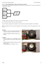
(OCR) – Option connector external relay terminals
The option connector is the upper D-SUB 15 Male connector on the rear side (see Section “Interface
connections” in the installation section). The Relay terminals are assigned as follows:
•
AUX2 – pins 3 and 4
•
AUX1 – pins 5 and 6
•
DSC CALL – pins 9 and 10
•
DSC ALARM – pins 14 and 15
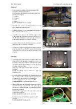
This section is consulted after the installation and sanity check of the connected external devices and that the
loading of the relays are within the specified values.
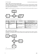
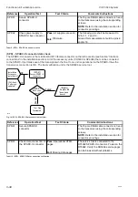
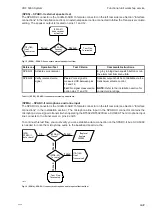
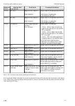
(OCR-01)
Secure option
connector screw
(OCR-03)
Relay test?
(Replace)
Replace BB
(base band
board)
Test Flow
Terminated
40431
(Installation)
external unit
and cables
Passed
OK
Failed
(OCR-02)
Initial state
(OCR-01)
Secure option
connector screw
(OCR-03)
Relay test?
(Replace)
Replace BB
(base band
board)
Test Flow
Terminated
40431
(Installation)
external unit
and cables
Passed
OK
Failed
(OCR-02)
Initial state
Fig. 11 (OCR) - Option connector relay test flow
Reference
Operation/Test
Test Criteria
Comments/instructions
The 15-pole DSUB cable connector is fixed
to the transceiver using the corresponding
screws.
NOTE: Refer to the installation section for
connector pin ratings.
The DSC CALL and DSC ALARM open
relay state is achieved if no active DSC
calls are active.
The open state of the AUX1 and AUX2
relays is achieved by selection of a channel
where the AUX relays has not been set as a
channel property via the service tool.
Pass:
Closing state is
recognized for all relays while
alarm tone is heard. Open
state is recognized when
sound stops.
Fail:
Otherwise.
OCVDR-03 Verify relay function
The relay test is executed via the menu
5.4
.
The closing state will be activated in 3
seconds.
OCR-01
Secure option
connector
OCR-02
Initialize relay states to
open state
Tabel 7 (OCR) - Option connector relay test tasks
Summary of Contents for RT5022
Page 2: ......
Page 4: ...VHF 5000 System 0930 ...
Page 16: ...Maintenance VHF 5000 System 2 2 ...
Page 70: ...Feature sales VHF 5000 System 4 2 ...
Page 82: ...Installation VHF 5000 System 5 12 0608 ...
Page 83: ...VHF 5000 System Installation 5 13 0608 ...
Page 84: ......


