SAGEMCOM MF 9841 Installation Manual Download Page 77

MF 9841  SG-DSK2/DSK3  14 – 3

F. Installation of the DSK firmware

(1) MFP booting operations after replacement

1)

Turn ON the power, and the main program error is displayed. 

2)

After 10 seconds from displaying the above error, the following
display is made. 

3)

The main program version is displayed, and the machine
enters the boot mode. 

(2) Boot mode operations

Install the DSK firmware as follows.

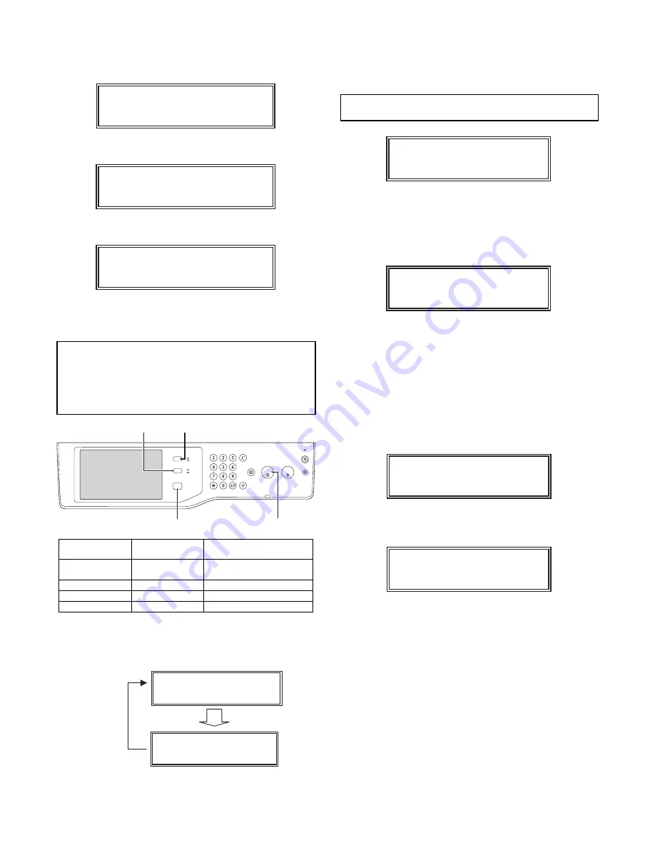
a. Operations and functions of the keys in the boot mode

NOTE:

Never press the C (clear) key in the boot mode.
Otherwise, may enter to the mode unrelated to

this procedure.
If, however, the C (clear) key was pressed by

mistake, press the home (MENU) key a few times
to return to the previous mode.

b. Function selection in the boot mode

The functions of the boot mode can be selected by pressing MENU
key as shown in the figure below. 

(3) DSK Firmware installing procedures in the boot 

mode

1)

Boot the machine in the boot mode. With "Version Check" dis-
played, press [MENU] key, and the machine enters the firm-
ware update mode. ("Firm Update" is displayed.) 

NOTE:

Make sure to confirm that "Firm Update From

USB Memory" is displayed.

Fig. Display of the SFU file

2)

Insert the USB memory with the installation or update firmware
file (SFU file) in it into the USB port of the machine, and press
[OK] key. 

Fig. Display of the SFU file 

3)

Select the target firmware file (SFU file) by using [UP] key and
[DOWN] key.
• When [OK] key is pressed with the directory name dis-

played, the control can enter the lower level directory. (How-
ever, one level lower only.)

4)

Press [OK] key. 
The selected firmware file (SFU file) is read. (It takes about
one minute.)

5)

After completion of reading, installation (update) of the firm-
ware is processed. 

* The code name of the firmware which is currently installed

(updated) is displayed sequentially on the right upper cor-
ner.

* The display may flash at a moment during installing (update)

procedures. This is a normal operation. 

Normal key name

Boot mode key 

name

Function

Start key 
(monochrome)

[OK] key

Executes the selected 
function or item. 

Home key

[MENU] key

Selects a menu.

Job status key

[UP] key

Selects an item.

System setting key

[DOWN] key

Selects an item.

Main Program Error!!

Emergency Prog Init

Please wait

Version Check

conf: xxxxxxxx

UP key

MENU key

OK key

DOWN key

LOGOUT

JOB STATUS

IMAGE SEND

PRINT

READY

DATA

DATA

LINE

SYSTEM

SETTINGS

HOME

Version Chec

k

conf: xxxxxxxx

Firm Update

From USB Memory

MENU key

MENU key

Firm Update

From USB Memory

Firm Update
> xxxxxxxx.sfu

Firm Update

Reading Data

Firm Update

IcuM

Writing Data

Summary of Contents for MF 9841

Page 1: ...SG GCX1 Large capacity tray 4 1 5 SG FNX3 Inner Finisher 5 1 6 SG PMX1 Punch module 6 1 7 SG BPX2 Paper pass unit 7 1 8 SG FNX4 Saddle stitch finisher 8 1 9 SG PMX2 Punch module 9 1 10 SG FEX2 Facsim...

Page 2: ...PS3 EXPANSION KIT SG PSX1 13 XPS EXPANSION KIT SG XEK1 14 BARCODE FONT KIT SG BF1 15 DATA SECURITY KIT SG DSK2 19 DATA SECURITY KIT SG DSK3 20 DESKTOP DOCUMENT MANAGER 5 LICENSE KIT SG LX5 21 KEYBOAR...

Page 3: ...STP FNX1 For finisher 12 STAPLE CARTRIDGE STP FNX4 For saddle Printer expansion 13 PS3 EXPANSION KIT SG PSX1 14 XPS EXPANSION KIT SG XEK1 SG MEX1 is required 15 BARCODE FONT KIT SG BF1 Image send expa...

Page 4: ...r lead wires to reduce impedance An electrical work is required Use of a step up transformer is also available In this case the capacity must be great enough for the max power consumption of the machi...

Page 5: ...d 2 Transit and delivery A Implements facility and manpower It is recommendable to use a forklift for bringing in the machine for safety If no forklift is available man power of four persons is requir...

Page 6: ...he SG CPX4 or SG CPX6 then unpack the main unit and securely place the main unit on the SG CPX4 or SG CPX6 before installing the main unit A Lock release 1 Tray rotation plate lock release 1 Pull out...

Page 7: ...color installation Be careful not to attach fingerprints or oily dirt on the DV roller sur face 1 Open the front cabinet 2 Check that the lock is released as shown in A Loosen the blue screw and open...

Page 8: ...n replacing developer use an extreme care not to drop developer on the drive section marked with 8 Install the DV cover in the arrow direction A When installing the DV cover be sure to engage the pawl...

Page 9: ...wer outlet 2 With the front cabinet open turn on the power switch on the operation panel 3 With the front cabinet open turn on the power switch on the operation panel 4 With the front cabinet still op...

Page 10: ...imes 2 Remove the heat seal 3 Open the front cabinet and insert each toner cartridge Be sure to install the color cartridges to their proper posi tions Avoid installation to a different color position...

Page 11: ...tall of the paper exit tray 1 Install the paper exit tray package part No 4 A to the upper section of the right door Install the paper exit full detection actuator package part No 5 B Be careful of th...

Page 12: ...key in the above screen to change the set tings The following settings can be configured 2 Tray size setup 1 Pull out the paper tray Gently pull the tray out until it stops If paper remains in the tr...

Page 13: ...he value of set item B 3 Press EXECUTE key The check pattern is printed out 4 Check the printed black image for any skew Measure the right angle level by using the six cross patterns printed in black...

Page 14: ...k image for any skew right angle in procedure 4 in advance If the image is skewed in the arrow direction of A shift the adjustment screw to X direction If the image is skewed in the arrow direction of...

Page 15: ...Image loss void area image off center adjustment Make a copy in the original table mode and in the RSPF DSPF mode Check to confirm that the image loss and the void area are in the range shown below N...

Page 16: ...0 28 mode 2 Select OC ADJ with the key button 3 Select the paper feed tray with paper in it with the key button Any paper size will do 4 Press EXECUTE key The color patch image adjustment pattern is p...

Page 17: ...fter the machine has finished calculating the adjustment amount for the front side the next screen appears where you can have the machine start reading SPF adjustment patterns for the back side 8 Set...

Page 18: ...ey Scanning of the DSPF adjustment pattern is started 10 The adjustment result screen is displayed 11 Press OK key The adjustment value is saved in EEPROM and RAM and the display is shifted to the end...

Page 19: ...Remark Descriptions on the factory service key button in the color bal ance automatic adjustment menu There are two kinds of the gamma target for the color balance automatic adjustment the factory tar...

Page 20: ...correction is dis played Press OK key The initial setting of the half tone image correction is per formed 9 When COMPLETE THIS PROCEDURE is displayed the adjustment operation is completed Cancel the...

Page 21: ...or balance adjustment result correctly If the color balance of each patch of the process black CMY mixed color is slightly shifted to Magenta it means that the adjustment is proper If the color balanc...

Page 22: ...d without adjustments shortening the servicing time N Necessary works before moving the machine 1 If the following options are installed remove all of them from the machine Saddle stitch finisher Larg...

Page 23: ...arts C Check the packed items 1 Check that all the items are included in the package 2 Installation Note before installation Before starting installation check to insure that the data lamp on the oper...

Page 24: ...overs of the both sides of the main unit 2 Put the main unit on the desk unit Use man power of four persons or more to lift the main unit Place the main unit on the desk unit slowly by fitting the ext...

Page 25: ...and left of the main unit front side and fix them with the fixing screws package part No 2 6 Replace the No 3 and No 2 trays to the original positions 7 Lift the connection plates and fix them with t...

Page 26: ...as pulled out E Connector connection 1 Remove the screw from the back of the main unit Remove the connector cover 2 Connect the connector 3 Split the removed connector cover along the perforated line...

Page 27: ...executed individually LEAD Print image lead edge image position adjustment OFFSET Print image off center adjustment When ALL is selected both of the above two items are executed simultaneously 4 Selec...

Page 28: ...n panel does not light up or blink A Turn off the power of the main unit 1 Turn OFF the power switch on the operation panel 2 Open the front cabinet Turn OFF the power switch in the front cabinet of t...

Page 29: ...unit MF 9626 9631 MF 9841 5 Install the connector cover and fix it with the screw 6 Install the exit tray unit A and the full detection actuator B package part No 2 Be careful of the installing direct...

Page 30: ...installation check to insure that the data lamp on the operation panel does not light up or blink A Turn off the power of the main unit 1 Turn OFF the power switch on the operation panel No Names of...

Page 31: ...the mounting plate upper package part No 1 to the right side of the main unit with the fixing screw A package part No 3 When installing put the rubber section of the mounting plate upper on the lower...

Page 32: ...closer to the main unit 2 Check to insure that the height adjustment check rib of the large capacity tray unit and the axis line of the mounting plate upper mounted to the main unit are in the same l...

Page 33: ...line of the mounting plate upper and insert the large capacity tray unit 7 Tighten the loosened screw D Connector connection 1 Remove the screw and remove the connector cover 2 Connect the connector a...

Page 34: ...de 3 Set the mark position of the auxiliary guide and the cas sette R to the size from A4 to LT and fix with the fixing screw flat screw At that time set the mark position of the auxiliary guide and t...

Page 35: ...ing procedures 1 Slowly pull out the tray until it stops 2 Loosen the stopper fixing screw 1 pc on the right lower side of the tray so that the stopper does not function 3 Pull out the tray again unti...

Page 36: ...w Fix the upper section with the fixing screw blue screw which was removed previously NOTE When the rear edge shaft is switched to B5 check to confirm that the side plates F R are already set to B5 If...

Page 37: ...ted individually LEAD Print image lead edge image position adjustment OFFSET Print image off center adjustment When ALL is selected both of the above two items are executed simultaneously 4 Select a p...

Page 38: ...arge capacity tray 2 Slowly insert the tray to the original position Then make a copy to check to insure that there is no more shift Repeat the procedures until there is no shift b When the shift is i...

Page 39: ...tems 1 Check that all the items are included in the package No Packed part names Quantity 1 Finisher fixing plate 1 2 Front slide rail 1 3 Dummy punch unit 1 4 Front open close cover 1 5 Punch cover 1...

Page 40: ...cabinet of the main unit 3 Disconnect the power plug of the main unit from the power out let B Removal of the paper holding arm unit 1 Push up the section A to disengage the pawl and remove the paper...

Page 41: ...he main unit frame with the hole in the finisher fixing plate package part No 1 7 Fix the right cover plate with the fixing screw package part No 8 Fix the side plate of the paper exit shifter with th...

Page 42: ...and the accuride Fix it with the coin screw package part No 10 13 Install the front open close cover package part No 4 to the front rail stay rotating shaft and fix it with the resin clip pack age par...

Page 43: ...lug of the main unit into the power outlet 2 Open the front cabinet Turn ON the power switch in the front cabinet of the main unit 3 Turn ON the power switch on the operation panel Second label Corner...

Page 44: ...nit Note before installation Before starting installation check to insure that the data lamp on the operation panel does not light up or blink Do not install the punch unit first because doing so woul...

Page 45: ...e power out let B Installation of the punch unit 1 Open the front cabinet 2 Open the front cover and slide the inner finisher to the left 3 Remove the coin screw and remove the finisher slide stopper...

Page 46: ...with the dove A and fix the punch unit with the screw which was fixing the dummy punch unit 10 Cut the lid of the punch cover with nippers 11 Remove the dust box 12 Fix the punch cover and the band t...

Page 47: ...ront cabinet Turn ON the power switch in the front cabinet of the main unit 3 Turn ON the power switch on the operation panel 2 1 Second label Corner R end fitting Lose the clearance First label Label...

Page 48: ...ting installation check to insure that the data lamp on the operation panel does not light up or blink A Turn off the power of the main unit 1 Turn OFF the power switch on the operation panel 2 Open t...

Page 49: ...ng arm which is easily removed alone and the paper holding arm holder C Installation of the interface pass unit 1 Open the front cabinet Remove the screws and remove the front cabinet upper 2 Disengag...

Page 50: ...t Install the interface left cabinet with the fixing screw A pack age part No 4 of the paper exit tray which was removed in procedure 4 7 Insert the reverse tray package part No 3 along the groove in...

Page 51: ...PX2 7 4 11 Insert the interface pass unit along the guide rail 12 Fix the interface pass disconnection preventing lever with the fixing screw A package part No 4 13 Go to the saddle finisher installin...

Page 52: ...xing material and remove the top case Remove the packing cushion and bundled items 2 Holding the upper part of the saddle stitch finisher by two peo ple pull up the saddle stitch finisher and make it...

Page 53: ...ided on the front side of the option desk is securely installed Make sure that the connection plate package part No 2 included in the package is securely installed A Replacement of the Operation Manua...

Page 54: ...into the connection hole If the guide pin is not inserted smoothly perform the follow ing adjustment 1 When the guide pin is not fit with the connection hole in the finisher 1 Loosen the fixing screw...

Page 55: ...and lower clearances between the main unit and the finisher are not even remove the screw one for each of the foot covers on the front rear sides and remove the foot cover 3 Loosen four fixing screws...

Page 56: ...l attachment 1 Attach the label to the position indicated in the figure For scanner package part No 10 For RSPF DSPF package part No 11 H Turn on the power of the main unit 1 Insert the power plug of...

Page 57: ...MF 9841 SG FNX4 8 6 2 Open the front cabinet Turn ON the power switch in the front cabinet of the main unit 3 Turn ON the power switch on the operation panel ON State of switch ON OFF...

Page 58: ...data lamp on the operation panel does not light up or blink A Turn off the power of the main unit 1 Turn OFF the power switch on the operation panel 2 Open the front cabinet Turn OFF the power switch...

Page 59: ...ove the screw and remove the front inner cover 5 Remove the screw and remove the dummy punch guide 6 Install the punch unit to the saddle finisher Fix the punch unit with the screw which was removed f...

Page 60: ...d close the front cover 9 Fix the front lower cover with a screw 10 Fix the rear cover with a screw 11 Install the saddle finisher to the main unit C Punch jam processing label attachment 1 Open the f...

Page 61: ...front cabinet of the main unit 4 Turn ON the power switch on the operation panel Second label Corner R end fitting Lose the clearance First label Label attachment reference Corner of the upper cabine...

Page 62: ...he main power switch to the OFF opsi tion 3 Remove the power plug of the main unit from the outlet B Attach the fax box unit to the rear part of the main unit 1 Remove the two screws from the rear cab...

Page 63: ...side E Attach the interface cable 1 Connect the interface cable to the control PWB unit Note Check that the connector is not obliquely inserted 2 Push the interface cable into the recessed portion of...

Page 64: ...and press the START key 3 Use the numeric keys to enter 06 in the sub code entry screen shown below and press the START key 4 Press the desired destination on the touch panel and press EXECUTE to hig...

Page 65: ...executed 6 After several minutes memory clear operation is completed and the YES button goes out Press the CA key to exit from the simulation mode Then the main unit is automatically rebooted K Connec...

Page 66: ...h and the main power switch After completion of 1 and 2 the Internet Fax send function from the main unit becomes enable To enable the Internet Fax send with the PC FAX driver the following steps 3 an...

Page 67: ...switch on the operation panel 2 Open the front cabinet Turn OFF the power switch in the front cabinet of the main unit 3 Disconnect the power plug of the main unit from the power out let No Name of p...

Page 68: ...rews 3 Attach the USB hub PWB unit part No 3 in the package with the removed screws 4 Connect the connector of the scan mother harness and con nect the mother PWB connection harness part No 4 in the p...

Page 69: ...ousing section of connector pull out it 2 Slowly pull the lead wire and disconnect the connector 3 There is a locking section on the reverse side Use care for that 5 Remove the screw and remove the pa...

Page 70: ...No 2 in the package to the operation base plate unit 6 Install the operation base plate unit to the main unit and fix it with the screws 7 Attach the front cabinet upper and fix it with the screws E A...

Page 71: ...ch Keyboard Select 4 Select your desired language and touch OK The keyboard layouts that can be selected are shown below 5 Press CA key to exit from system setting mode End of language setting The lay...

Page 72: ...ol PWB unit remove all cables 1 Push the location indicated in the illustration to unlock and remove the ozone filter cover from the right rear cabinet 2 Remove the screw from the right rear cabinet 3...

Page 73: ...e cable into the recessed portion of the sheet metal on the control PWB unit 3 Attach the snap band to the sheet metal of the control PWB unit 4 Push the control PWB unit into the main unit 5 Secure t...

Page 74: ...cabinet of the main unit 3 Turn ON the power switch on the operation panel 4 Check that the main unit recognize the installation of the scan ner function expansion kit SG ECK1 by SIM22 10 ON State of...

Page 75: ...on the operation panel does light up or blink A Turn off the power switches of the main unit 1 Turn the power switch located on the operation panel to the OFF position 2 After checking that the operat...

Page 76: ...he sheet metal of the control PWB unit 4 Push the control PWB unit into the main unit 5 Secure the unit with the two screws If the fax box unit is installed carry out step 6 addition ally 6 Fit the in...

Page 77: ...mory with the installation or update firmware file SFU file in it into the USB port of the machine and press OK key Fig Display of the SFU file 3 Select the target firmware file SFU file by using UP k...

Page 78: ...Update is failed Not Update Update itself is not executed Reason why Update is not executed No option device for the target firmware is not installed 7 Turn OFF the power to terminate the boot mode 8...

Page 79: ...the product key by the key operation of the copier machine a Touch PRODUCT KEY INPUT b Enter the product key with the 10 key and touch OK key 2 After completion of the product key entry turn OFF the...

Page 80: ...PS enter the product key by the key operation of the copier machine a Touch PRODUCT KEY INPUT b Enter the product key with the 10 key and touch OK key No Packed part names Quantity 1 CD ROM 1 2 Operat...

Page 81: ...s 1 Push the location indicated in the illustration to unlock and remove the ozone filter cover from the right rear cabinet 2 Remove the screw from the right rear cabinet 3 Remove the right rear cabin...

Page 82: ...d carry out steps 1 2 and 3 additionally 1 Connect the interface cable to the control PWB unit 2 Push the interface cable into the recessed portion of the sheet metal on the control PWB unit 3 Attach...

Page 83: ...E Turn on the main power switch of the main unit 1 Insert the power plug of the main unit to the outlet 2 Turn on the main power switch 3 Turn on the power switch located on the operation panel ON St...

Page 84: ...he control PWB unit remove all cables 1 Push the location indicated in the illustration to unlock and remove the ozone filter cover from the right rear cabinet 2 Remove the screw from the right rear c...

Page 85: ...f the control PWB unit 4 Push the control PWB unit into the main unit 5 Secure the unit with the two screws 6 Fit the interface cable into the right rear cabinet cover 7 Attach the right rear cabinet...

Page 86: ...e128 WideTT Regular 4 Code39HalfInch Regular 5 Code39OneInch Regular 6 Code39QuarterInch Regular 7 Code39SmallHigh Regular 8 Code39Slim Regular 9 Code39SmallLow Regular 10 Code39SmallMedium Regular 11...

Page 87: ...tor pro gram 2 When Solution Settings key is touched the menu below is displayed 3 When the Default Display Setting key is touched the screen for setting the default display that appears when the DOCU...

Page 88: ...n of the system setting or the key operator program b When Solution Settings key is touched the menu below is displayed c When External Account Setting key is touched the screen for setting the calcul...

Page 89: ......

Page 90: ...ows 95 Windows 98 Windows Me Windows NT 4 0 Windows 2000 Windows XP Windows Vista Windows 2000 Server Windows Server 2003 and Internet Explorer are trademarks or copyrights of Microsoft Corporation in...

Reviews: