


MF 9841 MF 9626/9631/9841 1 – 18
10) Check the copy color balance and density.
There are two methods to check the color balance and density.
(Method 1)
Use the servicing color test chart (UKOG-0317FCZZ/UKOG-
0317FC11) in the Text/Printed Photo mode (Manual) to check
the copy color balance and density. (Refer to the item of the
copy color balance and density check.)
(Method 2)
By printing the color balance adjustment sheet with SIM 46-21
and comparing each process (CMY) black patch color balance
with the black patch, the color balance adjustment can be
checked more precisely.
If the color balance of each patch of the process black (CMY
mixed color) is slightly shifted to Magenta, it means that the
adjustment is proper. If the color balance of the adjustment
pattern printed in this mode is slightly shifted to Magenta, it is
converted into the natural gray color balance by the color cor-
rection table in an actual copy mode. (When the color balance
target is DEF 1.)
If the automatic adjustment cannot obtain satisfactory results
of the copy color balance and density, use SIM 46-21 (ADJ
20C) (Manual adjustment).
11) Check the printer color balance and density.
There are two methods to check the color balance and density.
(Method 1)
Use SIM 64-5 to print the print test pattern and check the print
color balance and the density.
Set each setting value to the default and press [EXECUTE]
key, and the print test pattern is printed.
(Refer to the item of the printer color balance and density
check.)
(Method 2)
Use SIM67-25 to print the color balance adjustment sheet and
compare the black patch color balance of each process (CMY)
with the black patch. This procedure allows checking the color
balance adjustment result correctly.
If the color balance of each patch of the process black (CMY
mixed color) is slightly shifted to Magenta, it means that the
adjustment is proper. If the color balance of the adjustment
pattern printed in this mode is slightly shifted to Magenta, it is
converted into the natural gray color balance by the color table
in an actual printer mode. (When the color balance target is
DEF 1.)
If a satisfactory result on the print color balance and the den-
sity is not obtained with the automatic adjustment, execute the
manual adjustment (SIM 67-25) (ADJ 21B).
L. Function and operation check
Check that the following operations are normal.
;
/
%
$M
3
/CZ
1 2
0
/
.
-
,
+
*
)
(
'
&
%
$
#
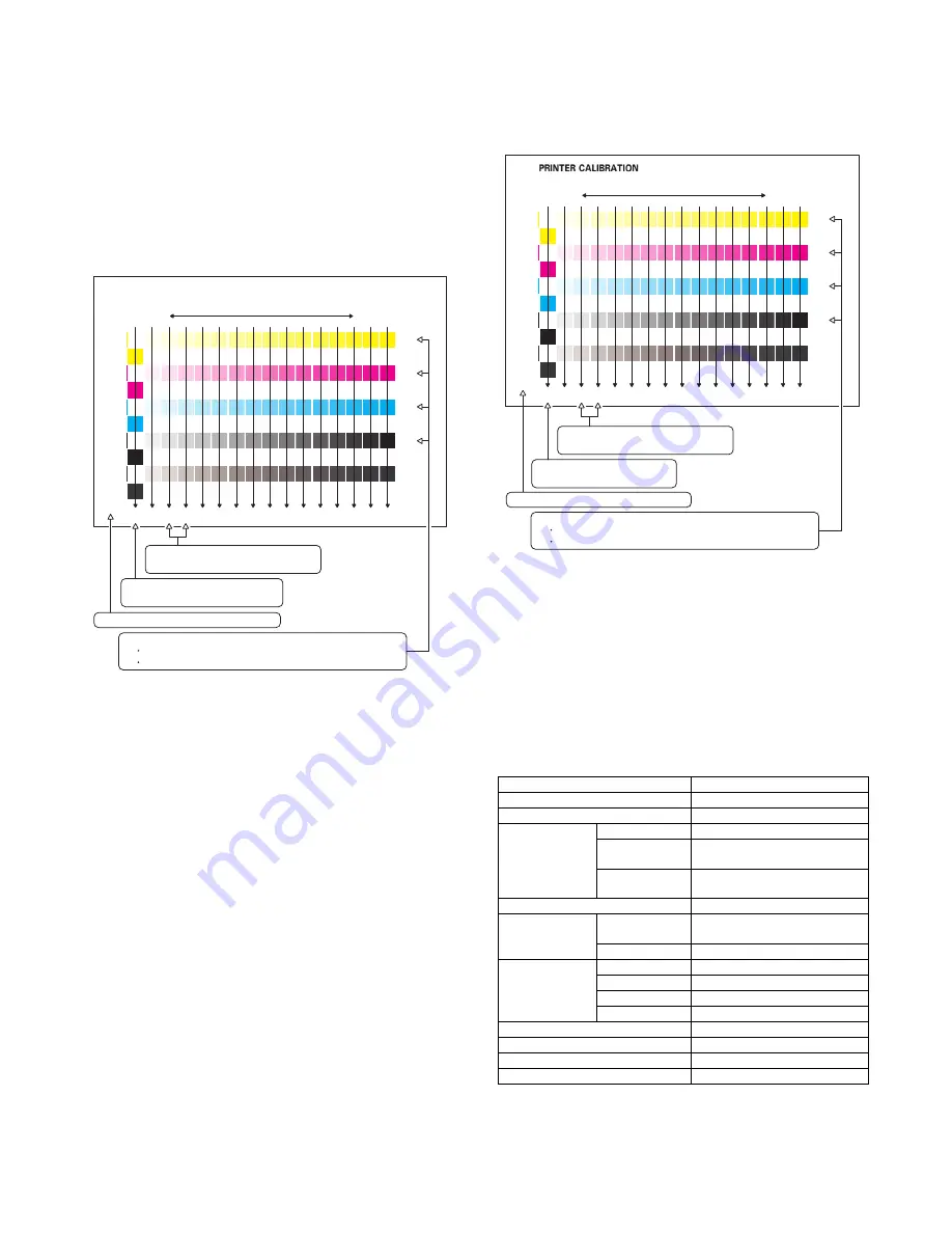
CMY
Blend
High density
Low density
Patch A of each of Y, M, C, and
BK are not copied.
2) Patch C or D of each of Y, C, M, and
BK is very slightly copied.
3) Patch for each of C, M, Y, BK
The patch density is identical between patches or not reversed.
The patch density is changed gradually.
1) The max. density section is not blurred.
Check item list
Equipped condition
Key-in (operation panel)
Display (operation panel)
Paper feed
operation
Hand feed
Main unit paper
tray
Desk unit paper
feed tray
With the desk unit installed
Paper size detection
Originals size
detection
Original table
mode
RSPF mode
RSPF operation/
two sided copy
S-S mode
D-S mode
S-D mode
D-D mode
Bookbinding operation
When the finisher is installed
Stapling operation
When the finisher is installed
Grouping operation
When the finisher is installed
Sorting operation
When the finisher is installed
;
/
%
$M
3
/CZ
1
2
0
/
.
-
,
+
*
)
(
'
&
%
$
#
CMY
Blend
High density
Low density
Patch A of each of Y, M, C, and
BK are not copied.
2) Patch C or D of each of Y, C, M, and
BK is very slightly copied.
3) Patch for each of C, M, Y, BK
The patch density is identical between patches or not reversed.
The patch density is changed gradually.
1) The max. density section is not blurred.
Summary of Contents for MF 9841
Page 89: ......


