S A G E M E T E R I N G , I N C .
O p e r a t i o n s a n d I n s t r u c t i o n M a n u a l
14
REV. 16-SIP/SRP
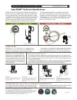
PROBE INSERTION GUIDELINE DRAWING
1
Choose the longest straight-run section of pipe avail-
able to allow a uniform, well-developed flow profile.
Allow for a
minimum
of 15 pipe diameters of straight
run upstream, and 5 diameters downstream, depend-
ing on the conditions. See chart on page 11. Note,
obstructions such as valves, blowers expanders and
PVC and HDPE pipes will require additional straight
run (contact factory for assistance). Avoid, if possible,
installations immediately downstream of bends, fans,
nozzles, heaters and especially valves, or anything
else installed in the line that may cause nonuniform
flow profiles and swirls. Otherwise signal output
errors could result, unless significantly more straight
run is provided, or in the absence of sufficient straight
run, Flow Conditioners (page 13) are in stalled (con-
tact Sage for assistance if needed). Refer to page 13 to
see the benefits of incorporating Flow Conditioners.
Insertion styles are available through Sage Metering,
Inc. with a standard 1/2" OD probe support assem-
bly; 3/4" is also available. Stan dard probe lengths
are 6", 12", 15", 18", 24", 30", 36" and 48". A common
method of mounting the probe assembly through
a pipe wall or duct (if ambient air) is with a compres-
sion fitting (STCF05). A Sage valve assembly (SVA05)
is useful and highly recommended for
pressurized applications or other gases,
such as Natural Gas. Flange mounting
is optionally available.
Sage insertion style flow meters can be assembled
and calibrated for use in virtually any size pipe or
duct (as small as 1”). Sage insertion flow meters
include a probe assembly that supports the sensing
element (a self-heated flow sensor and a tempera -
ture/reference sensor); a sensor drive circuit; micro -
pro cessor meter board, and trans mitter enclosure.
The probe assembly must be inserted into the correct
position in the pro cess gas flow conduit to allow the
gas to flow through the sensor “window” across the
sensor element. The “sensing point” or active part of
the sensor (0.5" from the end of the probe) should be
positioned as per the drawing below and the
Installation Depth Chart on page 15.
Installation Depth
The center of the pipe (assuming a well developed
turbulent flow profile) is fairly flat, and easy to
locate. See “Installation Depth Chart” on next page
to determine proper insertion depth.
Z
Y
X
4" PIPE SHOWN
LESS THAN IDEAL LOCATION
Contact Factory for Assistance
GOOD LOCATION
2,3
(See Installation Depth Chart for X and Y Dimension)
2. Probe should be inserted per Installation Depth Chart (see following page),
so sensors are in the center of the pipe.
3. The portion of the probe that remains outside of the pipe, is simply the factory
ordered probe length (i.e. “-15” = 15 inches) minus the “Y” dimension.
Center
of Pipe
PRIME
84
˚
F
13546
SCFM
467469670
SCF
88mW
1. SIP Industrial Meter shown in drawing. Note, probe is not bi-directional.
Summary of Contents for SIP
Page 2: ......
Page 6: ......
Page 7: ...Section GETTING STARTED A...
Page 8: ......
Page 25: ...Section STYLES AND FEATURES B...
Page 26: ......
Page 32: ......
Page 33: ...Section DRAWINGS C...
Page 34: ......
Page 41: ...Section DIAGNOSTICS D...
Page 42: ......
Page 47: ...Section WARRANTIES AND SERVICE WORK E...
Page 48: ......
Page 53: ...Section MODBUS F...
Page 54: ......
Page 63: ...G Section APPENDIX G...
Page 64: ......


