


O p e r a t i o n s a n d I n s t r u c t i o n M a n u a l
11
S A G E M E T E R I N G , I N C .
REV. 16-SIP/SRP
FLOW PROFILE AND INSTALLATION
CONSIDERATIONS
Insertion Flow Meters, although generally easier to
install that In-Line Flow Meters, require proper
installation, and a well developed flow profile, in
order to perform properly. Please refer to the section
on the following pages titled PROBE INSERTION
GUIDELINE DRAWING (page 14) and INSTALLA-
TION DEPTH CHART (page 15).
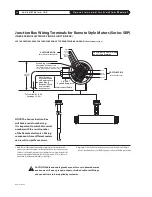
SAGE VALVE ASSEMBLY OPERATION
Valve assemblies (SVA05 and SVA05LP) are an op -
tional mounting hardware for Insertion Style Flow
Meters (see pages 38 and 39). They allow the removal
of insertion-style meters for service, cleaning, recali -
bration, relocation, etc. without the need to “shut-
down” your process. The probe insertion depth is
adjustable to permit sensor to be located at center
to optimize measurement accuracy. (Refer to PROBE
IN SERTION GUIDE LINE DRAWING and CHART, pages
14 & 15.) The ball valve will seal off leaks of the
process gas at the point of insertion after the probe
assembly has been removed. The assembly includes
a valve, threadolet, compression fitting with Teflon
ferrule, a cable restraint, and two collar clamps.
A threaded half coupling (3/4" FNPT) properly sized
to accom modate the isolation valve retractor assem-
bly must be fitted to the pipe/duct to which the
insertion probe will be inserted.
Avoid T-Fittings
since they will disturb the flow profile, and effec-
tively reduce the measurement area.
Direct thread-
ing together (or with necessary bushings) of the
retractor assembly may be required. In other cases,
the threadolet must be welded in place and a clear-
ance hole must be drilled through the pipe/ duct to
accept the probe assembly.
If the pipe/duct is under
pressure during installation, a hot tap drill (not
available through Sage Metering) may be required.
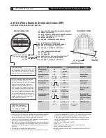
FLOW CONDITIONING AND STRAIGHT RUN
Although a minimum of 15 pipe diameters of
upstream straight run is commonly recommended,
to absolutely assure that the flow profile is well
developed at the point of measurement, either use
Flow Conditioners (standard in Sage In-Line Flow
Meters, 1/2" and larger, and also available as assem-
blies for Insertion Flow Meters, see page 13), or
consider additional straight run. The Chart below
provides examples of the amount of straight run
that would virtually assure that there are no flow
disturbances at the point of measurement.
N O T E :
Detailed
Drawings
are shown
on pages
38 & 39.
Insertion Flow Meter Application
IMPORTANCE OF FLOW CONDITIONING
Recommended Pipe Diameters Upstream
One 90˚ Elbow
Two 90˚ Elbows
in the same plane
Two 90˚ Elbows
in different planes
4:1 Area Reduction
4:1 Area Expansion
Multiple Disturbance
3
5
9
3
10
TBD
1
This column applies to In-Line Flow Meters, which come standard with built-in Flow Conditioners, as well as Insertion Meters,
when provided with upstream Captive Flow Conditioners (see page 13).
D I S T U R B A N C E
15
20
At least 40
15
At least 30
To Be Determined
WITHOUT
FLOW CONDITIONING
Minimum
Industry
Recommendation
WITH
FLOW
CONDITIONING
1
Sage
Recommendation
Summary of Contents for SIP
Page 2: ......
Page 6: ......
Page 7: ...Section GETTING STARTED A...
Page 8: ......
Page 25: ...Section STYLES AND FEATURES B...
Page 26: ......
Page 32: ......
Page 33: ...Section DRAWINGS C...
Page 34: ......
Page 41: ...Section DIAGNOSTICS D...
Page 42: ......
Page 47: ...Section WARRANTIES AND SERVICE WORK E...
Page 48: ......
Page 53: ...Section MODBUS F...
Page 54: ......
Page 63: ...G Section APPENDIX G...
Page 64: ......


