


S A G E M E T E R I N G , I N C .
O p e r a t i o n s a n d I n s t r u c t i o n M a n u a l
10
INSTALLATION AND MOUNTING
■
Check the Certificate of Conformance included
with your Sage Thermal Mass Flow Meter for
system pressure, temperature, gas composition,
power input, and signal output.
■
It is recommended that the flow meter be inserted in
a location of maximum straight run. It is suggested
that there be a minimum of 15 pipe diameters of
straight run upstream, and 5 diameters downstream,
depending on the conditions. See chart on page 11.
Note, obstructions such as valves, blowers, expand -
ers and PVC and HDPE pipes will require addition-
al straight run (contact factory for assistance).
■
Check the orientation
1
: Standard calibration flow
direction is left to right when facing the flow
meter. Gas flow direction is marked with an arrow
on in-line flow meters; UPSTREAM is marked on
insertion probes.
■
Do not rotate probe
1
, or errors may occur. If enclo-
sure is facing incorrectly, rotate the enclosure 180˚,
but do not rotate the probe. The UPSTREAM mark
still needs to be facing Upstream.
■
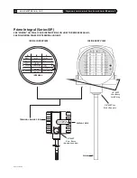
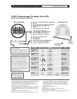
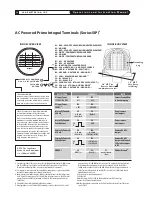
Hook up the system per the wiring diagram provid-
ed with your Sage flow meter (see inside of rear
compartment cover for terminal designation).
Double check that wiring for the proper power and
signal connections are correct.
■
Check that all plumbing and electrical hook-ups
are in accordance with OSHA, NFPA, and all other
safety requirements.
■
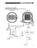
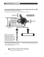
For Remote Style Meters (SRP) be sure the Remote
Electronics is matched with the Transmitter’s
Junction Box and its attached Probe or Flow
Body. There will be Metal Serial Number Tags
on both the Transmitter as well as the Remote
Electronics enclosure. Do not mismatch the seri-
al numbers of the Remote Electronics and the
Junction Box, or calibration errors will occur.
LOCATING PROPER WIRING DIAGRAM
1) Look at the sticker on your meter. The first three
digits describe the basic model that you have.
Refer to the appropriate page numbers below for
your wiring diagram
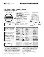
2) SIP: see page 19
3) SRP: see page 22 for input/output terminals;
see page 24 (Junction Box Wiring Terminals
for Remote Style Meters)
WIRING
Follow the instructions below to remove the rear cap
for wiring. CAUTION: Do not open the display side!
Before removing the rear cap to access the wiring
terminals it is essential to completely remove the
screw assembly on the side of the rear enclosure to
free up the threads so the lid can be removed. Note
there is a Red Tag attached to the screw assembly
stating
“Remove Screw Before Opening Lid”
.
After the wiring is completed (see pages 18 to 23
for wiring details), please close the lid, and reinsert
the screw assembly in the same manner.
Note:
See “Approvals” page for Hazardous Location
Approvals (DC Powered Meters Only)
REV. 16-SIP/SRP
1
The Integral Style of Sage Prime Insertion Meters have the Display oriented as shown on page 14.
If an alternate orientation of the display, or enclosure is required (ie. installation into a vertical pipe),
please furnish a sketch or drawing, and specify “ROTATE” on purchase order. However, if it is later
determined that the
enclosure
needs to be rotated, that procedure can be done in the field. However,
if the
display
needs to be rotated, then the meter must be sent back to Sage to be modified. Do not
attempt this in the field. An RMA will be required prior to returning the meter (see page 51). The
procedure for rotating the enclosure is as follows: Clamp the enclosure of the Prime in a vise with the
probe pointing up to the ceiling. Then take a 7/8 wrench and turn the probe to the proper orienta-
tion. Lock the probe into its new position with a set screw (not provided).
Summary of Contents for SIP
Page 2: ......
Page 6: ......
Page 7: ...Section GETTING STARTED A...
Page 8: ......
Page 25: ...Section STYLES AND FEATURES B...
Page 26: ......
Page 32: ......
Page 33: ...Section DRAWINGS C...
Page 34: ......
Page 41: ...Section DIAGNOSTICS D...
Page 42: ......
Page 47: ...Section WARRANTIES AND SERVICE WORK E...
Page 48: ......
Page 53: ...Section MODBUS F...
Page 54: ......
Page 63: ...G Section APPENDIX G...
Page 64: ......


