LIFT MODEL VISION AS 300 Rev001
6-14
6.4
Calling at floor control panel
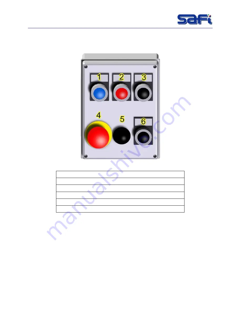
In the landing door there is a calling floor control panel.
The call floor system is a semi-automatic one.
Fig. 6-2 : Calling floor control panel
33. 1 – Auxiliary start button
34. 2 – Stop at floor button
35. 3 – Ascent button
36. 4 – Emergency Stop button
37. 5 – Control panel activator (selector)
38. 6 – Descent button
Use
To rise and descend the cabin it is necessary activate the calling floor control panel by
selector(
5
).
Then push the auxiliary START (
1
) to allow the cabin to move.
Push the ASCENT button (
3
) or DESCENT button (
6
) to go up or down respectively.
When the operator wants to stop the
cabin,
he only has to push the floor STOP (
2
) button
before reaching the desired floor.
If the floor STOP button is not pressed the machine continues run up to the last floor.
NOTE:
When the cabin is at a floor and remains inactive for 30 seconds, the cabin
automatically descent to the ground.
Summary of Contents for VISION AS 300
Page 2: ......
Page 4: ......
Page 43: ...LIFT MODEL VISION AS 300 Rev001 7 4 Fig 7 1 Dimension...
Page 68: ...LIFT MODEL VISION AS 300 Rev001 12 1 12 WIRING DIAGRAMS Fig 12 1 Wiring diagram Power supply...
Page 69: ...LIFT MODEL VISION AS 300 Rev001 12 1 Fig 12 2 Wiring diagram Motor power supply...
Page 70: ...LIFT MODEL VISION AS 300 Rev001 12 2 Fig 12 3 Wiring diagram Emergency circuit...
Page 71: ...LIFT MODEL VISION AS 300 Rev001 12 3 Fig 12 4 Wiring diagram Auxiliary...
Page 72: ...LIFT MODEL VISION AS 300 Rev001 12 4 Fig 12 5 4 Wiring diagram Auxiliary PLC logo expans...
Page 73: ...LIFT MODEL VISION AS 300 Rev001 12 5 Fig 12 6 Auxiliary circuit...
Page 74: ...LIFT MODEL VISION AS 300 Rev001 12 6 Fig 12 7 Wiring diagram Connectors C1 C2 C3...
Page 75: ...LIFT MODEL VISION AS 300 Rev001 12 7 Fig 12 8 Wiring diagram Terminal box electric panel...
Page 76: ...LIFT MODEL VISION AS 300 Rev001 12 8 Fig 12 9 Wiring diagram Cable call floor...
Page 77: ...LIFT MODEL VISION AS 300 Rev001 12 9 Fig 12 10 Wiring diagram Floors call connection...
Page 78: ...LIFT MODEL VISION AS 300 Rev001 12 10 Fig 12 11 Wiring diagram Box floor call connection...
Page 79: ...LIFT MODEL VISION AS 300 Rev001 12 11 Fig 12 12 Wiring diagram Box Fencing connection...
Page 80: ...LIFT MODEL VISION AS 300 Rev001 12 12 Fig 12 13 Wiring diagram Cable fancing call...
Page 81: ...LIFT MODEL VISION AS 300 Rev001 12 13 Fig 12 14 Main electrical box components...
Page 82: ...LIFT MODEL VISION AS 300 Rev001 12 14 Fig 12 15 Material list 1...
Page 83: ...LIFT MODEL VISION AS 300 Rev001 12 15 Fig 12 16 Material list 2...


