19
XL-TG10153BM-en-US Rev A · 2013-06-27 · Amendments and Errors Reserved · © SAF-HOLLAND, Inc., SAF-HOLLAND, HOLLAND, SAF,
and logos are trademarks of SAF-HOLLAND S.A., SAF-HOLLAND GmbH, and SAF-HOLLAND, Inc.
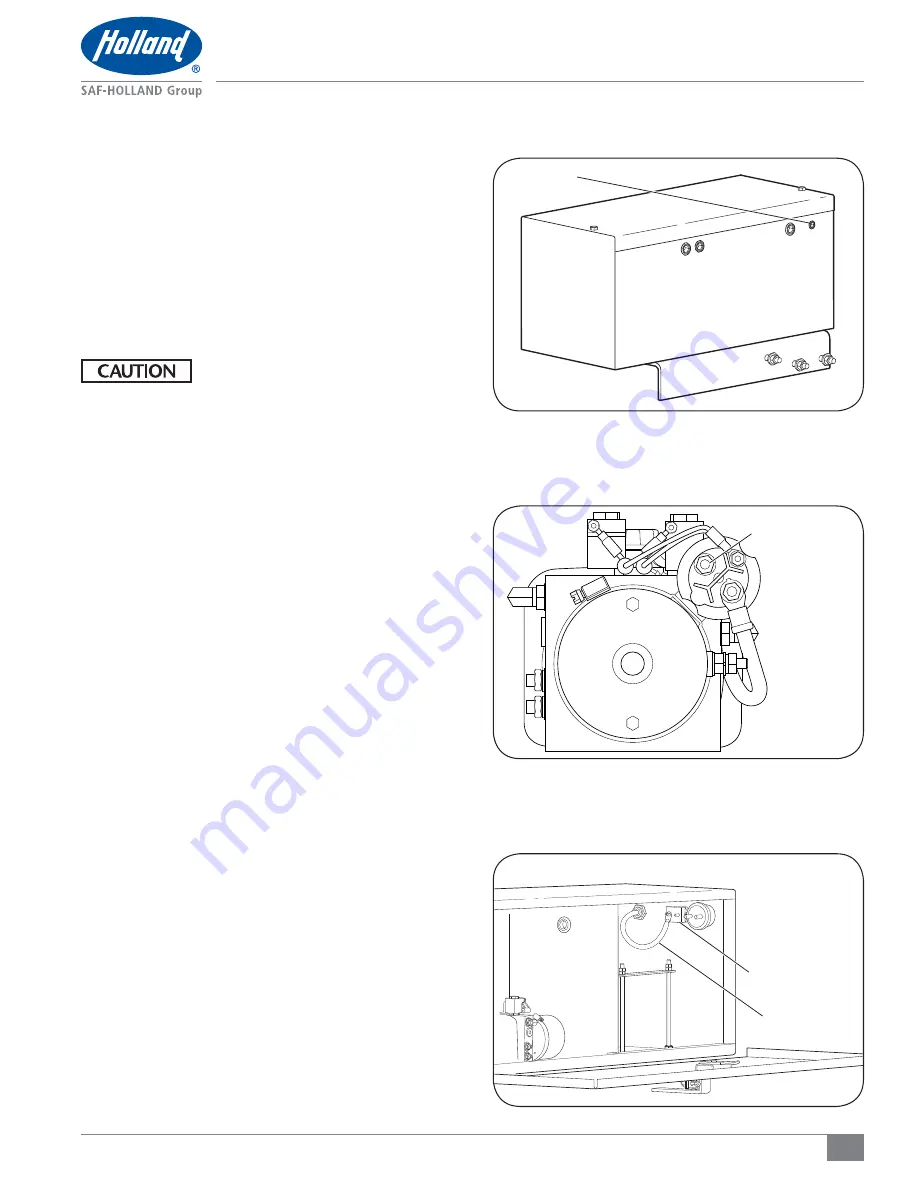
Figure 31
Electrical Installation
Figure 33
Figure 32
11. Electrical Installation
1. Identify the power source from either the truck or the
connector at the front of the trailer on which your liftgate
is to be installed.
2. Feed one end of the power cable through the strain relief
in the pump box
(Figure 31)
.
3. Strip the protective rubber coating from the end of the
cable that’s inside the pump box.
4. Install the cable end on the bare end of the cable and
crimp securely into place.
Failure to properly secure the cable and
may result in electrical overload which,
if not avoided, could result in electrical
component damage.
5. Connect the load end of the power cable as follows:
a. For a pump box without batteries connect the cable
end to the power side of the motor start solenoid
(Figure 32)
.
b. For a pump box with batteries connect the cable end to
the power side of the 150A circuit breaker in the pump
box
(Figure 33)
.
6. Route the power cable along the underside of the vehicle
to the front and secure to cross members.
a. For truck installations the cable needs to be long
enough to reach the vehicle battery.
b. For trailer installations the cable needs to be long
enough to reach the connector.
GROMMET
CONNECT POWER
CABLE
CIRCUIT BREAKER
POWER CABLE


