17
XL-TG10153BM-en-US Rev A · 2013-06-27 · Amendments and Errors Reserved · © SAF-HOLLAND, Inc., SAF-HOLLAND, HOLLAND, SAF,
and logos are trademarks of SAF-HOLLAND S.A., SAF-HOLLAND GmbH, and SAF-HOLLAND, Inc.
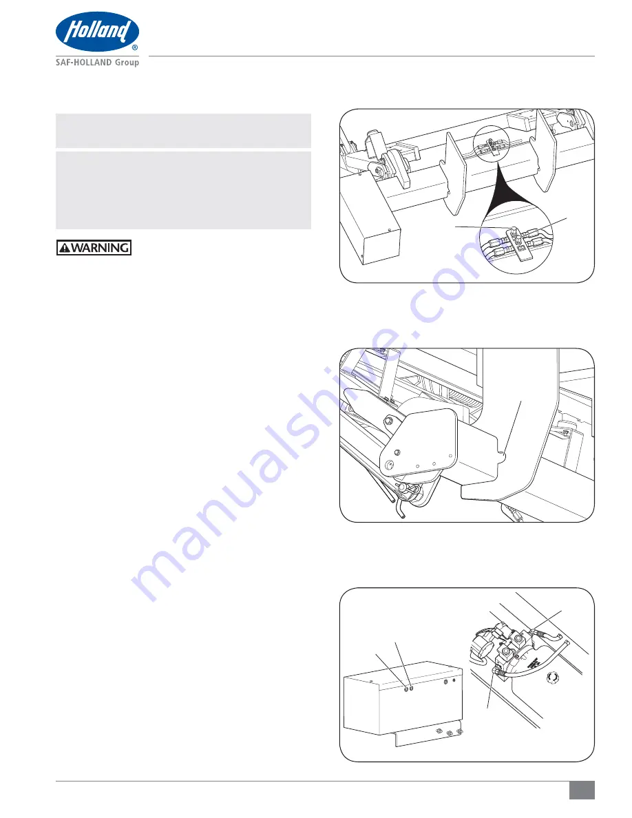
Figure 27
Hydraulic Hose Installation
9. Hydraulic Hose Installation
NOTE:
Packaged with your liftgate, there are two (2)
hoses of equal length.
IMPORTANT:
Hydraulic hoses and hydraulic fittings are
shipped with end caps installed which
MUST be removed before installation.
IMPORTANT:
DO NOT remove the cylinder lock strap
that supports the platform and lift frame.
Failure to support the platform and lift
frame could result in a crush or pinch
hazard, which if not avoided, could
result in death or serious injury.
1. Connect a hose to the ‘A’ fitting on the main tube, feed
through the supplied abrasive sleeve, then through the
hole in the attaching plate
(Figure 26 and 27)
.
2. Feed the hose through the grommet hole in the pump
box.
(Figure 28).
3.
Connect the hose to the ‘A’ port on the power pack
(Figure 29).
4. Connect a hose to the ‘B’ fitting on the main tube, feed
through the supplied abrasive sleeve, then through the
hole in the attaching plate
(Figure 26 and 27).
5
.
Feed the hose through the grommet hole in the pump
box
(Figure 28).
6. Connect the hose to the ‘B’ port on the power pack
(Figure 28).
A
B
ATTACHING
PLATE HOLE
Figure 28
Figure 26
A
B
PORT A
PORT B


