background image

13

XL-TG10153BM-en-US Rev A · 2013-06-27 · Amendments and Errors Reserved · © SAF-HOLLAND, Inc., SAF-HOLLAND, HOLLAND, SAF, 
and logos are trademarks of SAF-HOLLAND S.A., SAF-HOLLAND GmbH, and SAF-HOLLAND, Inc.

Liftgate Installation

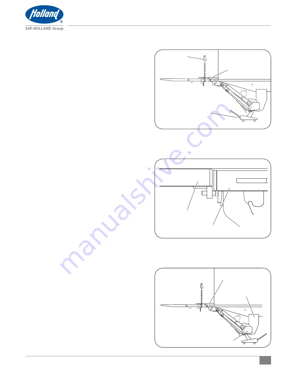
Figure 18

Figure 17

Figure 16

ANGLE BRACKET

HOIST

FLOOR JACK

PLATFORM

DECK EXTENSION

DECK EXTENSION

ATTACHING PLATE

MAIN TUBE

4.  Lift the platform with the hoist and place a floor jack 

under the main tube 

(Figure 16)

.

5.  While maintaining a 1/4" (6 mm) gap with a spacer 

between the deck extension and the platform, center the 
platform on the vehicle. Continue to support the platform 
with the floor jack.

6.  The platform MUST be flush and parallel with the deck 

extension while maintaining a 1/4" (6 mm) gap between 
the deck extension and the platform 

(Figure 17)

.

7.  Ensure the liftgate's entire length is positioned correctly 

from the top of the deck extension to the top of the main 
tube 

(Figure 18)

8.  Use floor jacks to reposition the main tube parallel to the 

vehicle deck both front to rear and left to right.

Summary of Contents for Holland TL Series

Page 1: ...XL TG10153BM en US Rev A Installation Manual TL Series Liftgate 4000 5000 Lb Capacity ...

Page 2: ...XL TG10153BM en US Rev A 2013 06 27 Amendments and Errors Reserved SAF HOLLAND Inc SAF HOLLAND HOLLAND SAF and logos are trademarks of SAF HOLLAND S A SAF HOLLAND GmbH and SAF HOLLAND Inc ...

Page 3: ...y also be ordered directly from SAF HOLLAND the address is shown on the back cover Notes Cautions and Warnings You must read and understand all of the safety procedures presented in this manual before operating or starting any work on the liftgate NOTE In the United States workshop safety requirements are defined by federal and or state Occupational Safety and Health Act Equivalent laws may exist ...

Page 4: ... 5 Check for slippery surfaces before stepping off the liftgate platform 6 NEVER jump off the liftgate 7 In an emergency situation release the control switch to stop the liftgate operation 8 SAF HOLLAND liftgates require routine service inspection and maintenance in order to maintain optimum performance proper operation and to identify normal wear Failure to properly engage the vehicle parking bra...

Page 5: ...ided could result in death or serious injury 8 Pressure can remain in a hydraulic system after the power source and pump have been shut down Ensure that there is no pressure in any of the hydraulic cylinders or hoses before performing work on components or disconnecting any hoses Figure 3 Failure to depressurize the hydraulic system could result in fluid injection into the skin which if not avoide...

Page 6: ...roperties Tensile Strength 72k psi 496 MPa Yield Strength 60k psi 414 MPa Charpy V Notch 20 ft lbs 27 N m at 0o F 17 7o C Elongation 22 Figure 4 LACK OF FUSION OF ANY KIND IN THIS AREA IS NOT ACCEPTABLE AT ANY TIME PENETRATION AS MEASURED THROUGH SEAM TARGET PENETRATION TO BE 10 OF THINNEST MATERIAL FROM INTERSECTION OF FILLET AS SHOWN TARGET PENETRATION The recommended welding gas for gas metal a...

Page 7: ...onth Code After November 1 2008 92 02 312 0123 Sequence Number Day of Year Year Code Facility Code 3 Liftgate Model and Serial Number Location Each SAF HOLLAND liftgate has a stamped metal tag that identifies the liftgate model and serial number Figure 5 This tag is attached to the front roadside of the main tube Figure 6 In order to properly identify your HOLLAND liftgate and its components when ...

Page 8: ...ology 15 4 Liftgate Terminology 1 ITEM DESCRIPTION 1 Control Station 2 Inner Platform 3 Outer Platform 4 Adjusting Bolts 5 Torsion Spring 6 Compression Member 7 Roller Opener 8 Parallel Arms 9 Lift Frame ITEM DESCRIPTION 10 Lift Cylinder 11 Step Braces 12 Pump Box Mount 13 Pump Box 14 Travel Latch 15 Main Tube 16 Attaching Plates 17 Deck Extension 18 Rear Impact Guard 2 3 4 5 6 7 8 9 10 12 13 11 1...

Page 9: ...uired loads 1 Remove bumper step or any protrusions that would prevent the deck extension from being mounted flush against the rear doorsill 2 Follow the frame cutout requirements for your preferred installation Figures 7 or 8 NOTE Standard Mount Additional frame modifications may be necessary depending on the application Figures 7 or 8 STANDARD MOUNT TRUCK INSTALL POST 12 304 mm 14 355 mm FOR 61 ...

Page 10: ...t required loads 1 Remove bumper step or any protrusions that would prevent deck extension from being mounted flush against the rear doorsill 2 Follow the frame cutout requirements for your preferred installation Figures 9 or 10 NOTE Flush Mount Deck extension replaces the rear sill and is mounted flush with the rear frame posts Figures 9 or 10 FLUSH MOUNT TRUCK INSTALL FLUSH MOUNT TRAILER INSTALL...

Page 11: ...vehicle chassis This ensures that the liftgate is mounted on the centerline of the vehicle 3 After the deck extension is positioned correctly prep the vehicle frame With a grinder remove any galvanized paint within 1 to 4 25 to 101 mm of the weld surface 4 Tack weld into position 5 Weld per Figures 11 and 12 NOTE When welding is required ensure that the battery ground cable is disconnected and tha...

Page 12: ...ets to the deck extension with 18 457 mm of overhang These brackets will help maintain alignment Figure 14 NOTE When welding is required ensure that the battery ground cable is disconnected and that all electrical equipment is completely electrically isolated before welding is initiated Failure to isolate electrical equipment from ground prior to welding could result in overload which if not avoid...

Page 13: ...the main tube Figure 16 5 While maintaining a 1 4 6 mm gap with a spacer between the deck extension and the platform center the platform on the vehicle Continue to support the platform with the floor jack 6 The platform MUST be flush and parallel with the deck extension while maintaining a 1 4 6 mm gap between the deck extension and the platform Figure 17 7 Ensure the liftgate s entire length is p...

Page 14: ...he weld surface 11 Weld the liftgate attaching plates to the main tube and to the vehicle frame per Figure 20 NOTE When welding is required ensure that the battery ground cable is disconnected and that all electrical equipment is completely electrically isolated before welding is initiated Failure to isolate electrical equipment from ground prior to welding could result in overload which if not av...

Page 15: ...mbly brackets against the truck crossmembers NOTE When welding is required ensure that the battery ground cable is disconnected and that all electrical equipment is completely electrically isolated before welding is initiated Failure to isolate electrical equipment from ground prior to welding could result in overload which if not avoided could result in property damage 3 After the main tube is po...

Page 16: ... the battery ground cable is disconnected and that all electrical equipment is completely electrically isolated before welding is initiated Failure to isolate electrical equipment from ground prior to welding could result in overload which if not avoided could result in property damage 3 After the main tube is positioned correctly prep the vehicle frame With a grinder remove any paint or galvanizi...

Page 17: ...port the platform and lift frame could result in a crush or pinch hazard which if not avoided could result in death or serious injury 1 Connect a hose to the A fitting on the main tube feed through the supplied abrasive sleeve then through the hole in the attaching plate Figure 26 and 27 2 Feed the hose through the grommet hole in the pump box Figure 28 3 Connect the hose to the A port on the powe...

Page 18: ...the control station cable through the strain relief on the back of the pump box Figure 29 4 Connect the green wire from the control station cable to the power side terminal of the pump solenoid Figure 28 5 Connect the white wire from the control station cable to the coil with white wire from the diode harness Figure 30 6 Connect the black wire from the control station cable to the coil with black ...

Page 19: ...he bare end of the cable and crimp securely into place Failure to properly secure the cable and may result in electrical overload which if not avoided could result in electrical component damage 5 Connect the load end of the power cable as follows a For a pump box without batteries connect the cable end to the power side of the motor start solenoid Figure 32 b For a pump box with batteries connect...

Page 20: ...are the cable ends per Steps 3 and 4 NOTE Ensure the master disconnect switch is in the OFF position prior to connecting the battery 7 4 Connect the cable to the master disconnect switch circuit breaker and battery For truck installation Figure 35 7 1 Mount the connector to the front of the trailer adjacent to the airline connections 7 2 Cut the cable at the connector position and prepare the cabl...

Page 21: ...rap Tighten the nuts on the threaded bars to ensure the batteries are securely seated 3 Connect the red positive 12 304 mm battery cable to the positive terminals of the battery Figure 36 4 Connect the black negative 12 304 mm battery cable to the negative terminals of the battery Figure 36 IMPORTANT Verify the master disconnect switch is OFF before connecting it to the battery Failure to turn the...

Page 22: ...k ground cable from the ground cable kit to the ground cable stud on the back of the pump box Figure 39 9 Drill a 3 8 9 mm diameter hole in a crossmember close enough to the pump box to allow the ground cable end to be connected to the pump box and vehicle crossmember Figure 40 10 Install the other end of the ground cable onto the vehicle crossmember with the provided hardware Figure 41 BLACK GROU...

Page 23: ...iary Battery and Cable Installation Figure 42 Figure 43 11 Connect the black ground cable that is already installed on the back of the pump box to a negative terminal on the battery Figure 42 12 Ensure that the battery connections are properly made Figure 43 NOTE After tightening all electrical connections apply a dielectric grease to prevent corrosion BLACK 12 304 mm GROUND CABLE POWER TO PUMP ...

Page 24: ...44 6 Support the platform from underneath and remove the temporary brackets that have been holding the platform in position that were installed in Section 6 Figure 14 7 Remove both roadside and curbside leveler lock straps from the front face of the main tube by grinding off the welds Figure 45 8 Remove the supports from underneath 9 Push the control station toggle to the DOWN position and lower t...

Page 25: ...sure that the battery ground cable is disconnected and that all electrical equipment is completely electrically isolated before welding is initiated Failure to isolate electrical equipment from ground prior to welding could result in overload which if not avoided could result in property damage 1 After verifying that the liftgate installation is proper sound and safe install the two 2 latch pins t...

Page 26: ...e SAF HOLLAND 5 127 mm notched step brace skip to Step 4 Figure 50 3 If installing a rear impact guard weld 2 x 2 x 1 4 wall x 3 50 x 50 x 6 x 76 mm long tube spacers on the ends of the deck extension Figure 51 These spacers will provide clearance for the rear impact guard while the liftgate is in operation IMPORTANT Ensure the overall width of the deck extension and step braces is within vehicle ...

Page 27: ...ce 3 Weld the roller opener into position Figure 54 and 55 Repeat these Steps 1 3 for the opposite side NOTE When welding is required ensure that the battery ground cable is disconnected and that all electrical equipment is completely electrically isolated before welding is initiated Failure to isolate electrical equipment from ground prior to welding could result in overload which if not avoided ...

Page 28: ... Turn the liftgate master disconnect switch to the OFF position Failure to turn the liftgate master disconnect switch to the OFF position before working under the liftgate could allow for the operation of the liftgate which if not avoided could result in death or serious injury 6 Slide the rear impact guard under the liftgate lift frame and position the rear impact guard mounting plates Figure 57 ...

Page 29: ...to putting the vehicle into service install all supplied decals listed in the table below and Figures 60 and 61 CURBSIDE A D E F H C B G B D A DECAL QTY ENGLISH FRENCH DESCRIPTION A 2 XB 51913 XB 51914 Max Capacity 4000 2 XB 58882 XA 58883 Max Capacity 5000 B 2 XB 51170 XB 57067 Pinch Point C 1 XB 54995 XB 64388 High Pressure Fluid D 2 XB 50528 XA 62611 Safety Latches E 1 XB 50346 XB 50353 Warning...

Page 30: ...30 XL TG10153BM en US Rev A 2013 06 27 Amendments and Errors Reserved SAF HOLLAND Inc SAF HOLLAND HOLLAND SAF and logos are trademarks of SAF HOLLAND S A SAF HOLLAND GmbH and SAF HOLLAND Inc Notes ...

Page 31: ...31 XL TG10153BM en US Rev A 2013 06 27 Amendments and Errors Reserved SAF HOLLAND Inc SAF HOLLAND HOLLAND SAF and logos are trademarks of SAF HOLLAND S A SAF HOLLAND GmbH and SAF HOLLAND Inc Notes ...

Page 32: ...al component assembly SAF HOLLAND Original Parts are tested and designed to provide maximum performance and durability Will fits look alikes or worse yet counterfeit parts will only limit the performance potential and could possibly void SAF HOLLAND s warranty Always be sure to spec SAF HOLLAND Original Parts when servicing your SAF HOLLAND product SAF HOLLAND USA INC 1950 Industrial Blvd Muskegon...

Reviews: