15
XL-TG10153BM-en-US Rev A · 2013-06-27 · Amendments and Errors Reserved · © SAF-HOLLAND, Inc., SAF-HOLLAND, HOLLAND, SAF,
and logos are trademarks of SAF-HOLLAND S.A., SAF-HOLLAND GmbH, and SAF-HOLLAND, Inc.
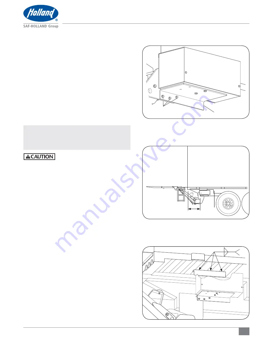
Pump Assembly Installation
Figure 23
Figure 22
Figure 21
8. Pump Assembly Installation
Main Tube Mount, Standard Option
Truck and Trailer Installation
1. Using the supplied fasteners, fasten the pump assembly
to the end of the main tube
(Figure 21)
.
2. Torque nuts to 30-40 ft.-lbs. (41-54 N•m).
Side Mount Box
1. Locate the pump box behind the curbside mud flap under
the vehicle no more than 4' (1219 mm) from the back of
the vehicle and 6" (152 mm) in from the curbside of the
vehicle body
(Figure 22).
2. Position the pump assembly brackets against the
truck crossmembers.
NOTE:
When welding is required, ensure that the battery
ground cable is disconnected and that all electrical
equipment is completely electrically isolated
before welding is initiated.
Failure to isolate electrical equipment
from ground prior to welding could result
in overload which, if not avoided, could
result in property damage.
3. After the main tube is positioned correctly, prep the vehicle
frame. With a grinder, remove any paint or galvanizing
within 1" to 4" (25-101 mm) of the weld surface.
4. Weld the pump box to the vehicle crossmembers
(Figure 23).
5. Touch up paint as required. For galvanized liftgates, touch
up in accordance with the most recent release of ASTM
A 780: Standard Practice for Repair of Damaged and
Uncoated Areas of Hot Dip Galvanized Coatings, which
specifies the use of zinc-rich paints.
4'
(1219 mm)
1/4"
TYP
MAIN TUBE BRACKET
SUPPLIED
FASTENERS


