Instruction manual V 2.3
22
PWM 230 - PWM 400 - PWM 400/7.5
Instruction manual
tb
Setting of lack of water blockage latency time [s]
GP
Setting of proportional gain of the PI
GI
Setting of integral gain of the PI
FS
Setting of the max. rotation frequency of the electro pump [Hz]
FL
Setting of the min. rotation frequency of the electro pump [Hz]
Ft
Setting of low flow rate threshold
CM
Setting of role exchange policy on booster set with 2 pumps
AE
Setting of enabling of anti-block/anti-frost function
i 1
Setting of input 1 function
i 2
Setting of input 2 function
i 3
Setting of input 3 function
P1
Setting of auxiliary set point pressure [bar]
O 1
Setting of output 1 function
O 2
Setting of output 2 function
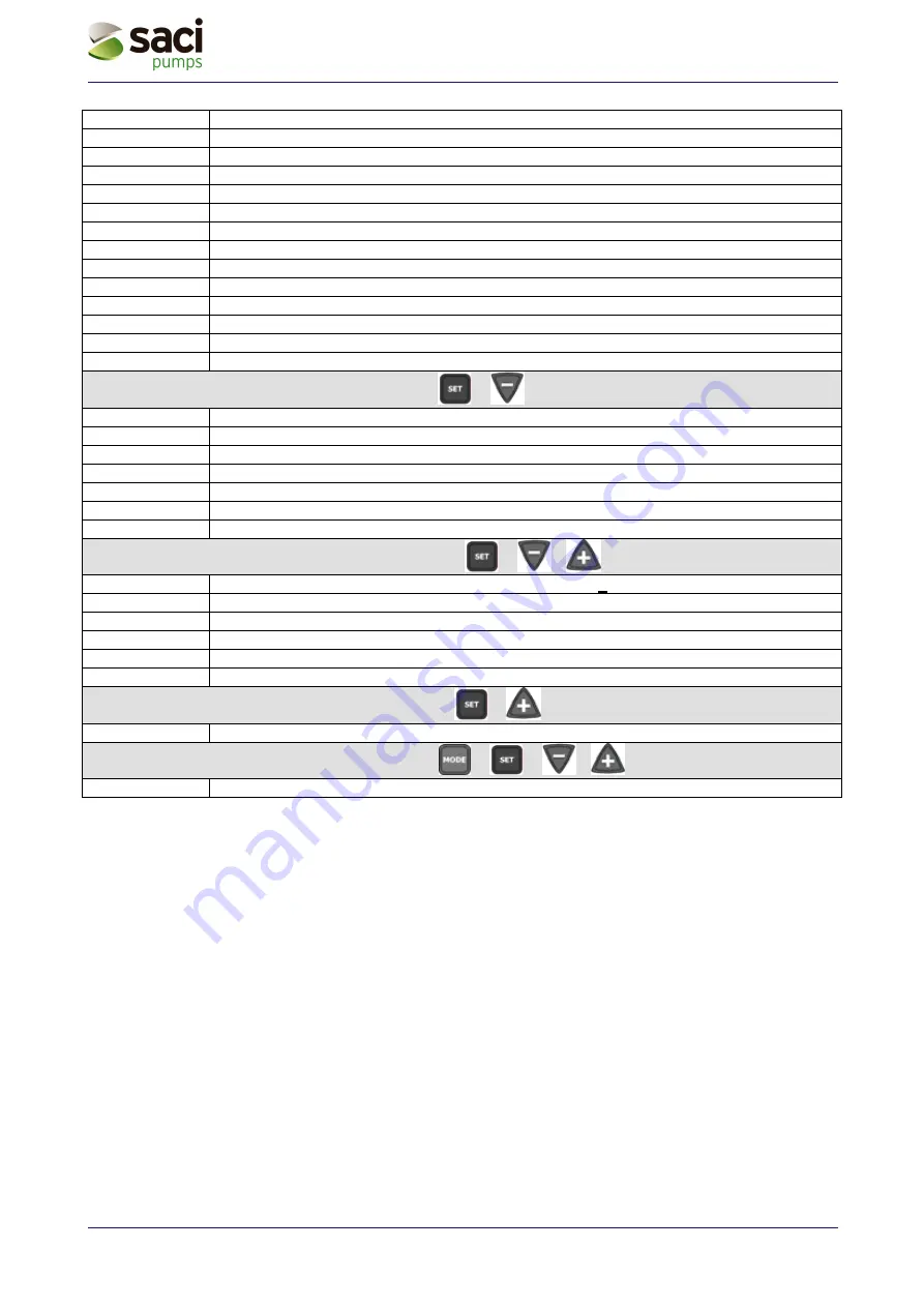
DISPLAY (keys
&
for 2 sec.)
UF
Display of the flow (duplicated in manual mode)
ZF
Display of zero flow (duplicated in manual mode)
FM
Display of the max. rotation frequency [Hz]
tE
Display of the power output stages temperature [°C]
bt
Display of the printed circuit’s temperature [°C]
GS
Display of running status
FF
Display of fault and block history queue
Access to manual mode (keys
&
&
5 seconds)
FP
Setting of manual mode test frequency (in Hz). Must be < to the current FS value
UP
Display of pressure [bar]
C1
Display of the electro pump’s phase current [A]
rt
Setting of direction of rotation
UF
Display of flow
ZF
Display of zero flow
Restoring the factory settings (keys
&
for 2 sec when turning on)
EE
Saving and reading back of factory settings on the EEPROM
System reset (keys
&
&
&
)
ZF
General reset (ZF appears when leaving reset and the system is restarted)
Table 8: Meaning of the messages shown on the display

