Instruction manual V 2.3
21
PWM 230 - PWM 400 - PWM 400/7.5
Instruction manual
The name of the parameter appears at first for a second. Thereafter the hundreds are shown and, finally, the
tens and the units are shown. The Hundreds are represented on the right digit, while the left one is off;
thereafter the left digit represents the tens while the right digit represents the units. Three-digit numbers are
completely displayed for three times in 5 seconds, and then the two-letters parameter name will be displayed
for one second. During value modification only tens and units of three-digit parameter values are shown.
After value modification has completed, parameter values are displayed on three digits again.
For quantities that contain a decimal digit the digit is displayed for values up to 9,9, while when this value is
exceeded only tens and units are displayed.
WARNING
:
When the PWM is configured for connection to another PWM or to a "Da Vinci" controller
board (see sections 5.1.2.6, 5.1.2.6.1 and 5.1.2.6.2) but the communication doesn't work,
the display blinks when the "Go" or "Sb" status codes are displayed.
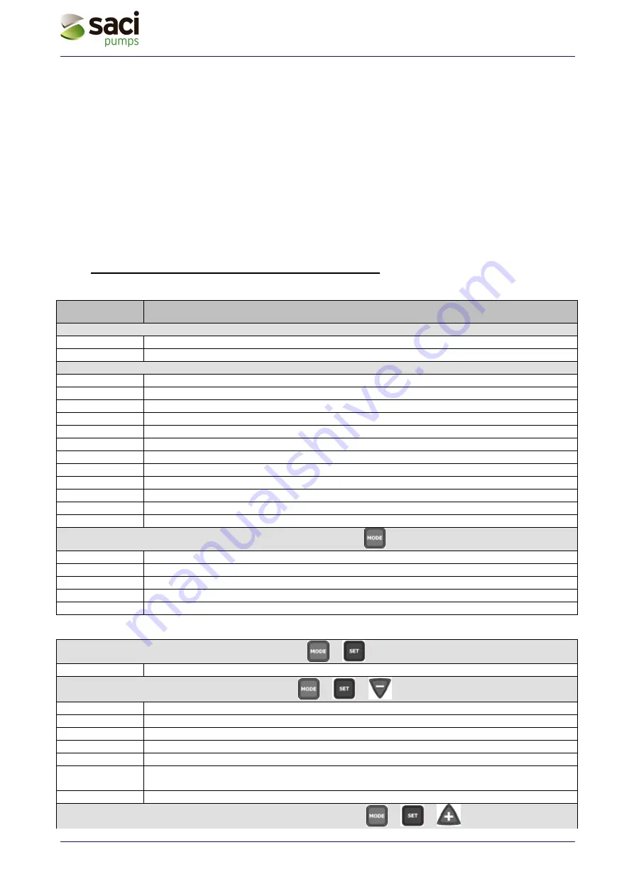
3.3 Meaning of the messages shown on the display
User displays and settings (
&
keys for 2 seconds)
SP
Setting the set-point pressure [in bar]
Installer displays and settings (
&
&
keys for 5 seconds)
rC
Setting the rated current of the electro pump [A]
Fn
Setting the rated frequency of rotation of the electro pump [Hz]
rt
Setting the direction of rotation (duplicated in manual mode)
od
Setting the PWM operating mode
rP
Setting the pressure drop for restarting [bar]
Ad
Setting the interconnection address (necessary on booster set with more than one pump
with exchange)
Eb
Enabling the booster pump
Technical assistance displays and settings (keys
&
&
5 seconds)
Identifier
Description
Indication on the display in normal operation
Go
Electro pump operating
Sb
Electro pump not operating
Error and Status conditions
bL
Blockage due to lack of water
bP
Blockage due to missing pressure sensor
LP
Blockage due to low supply voltage
HP
Blockage due to high supply voltage
EC
Blockage due to incorrect setting of the rated current (rC) or rated frequency (Fn)
oC
Blockage due to current overload in the electro pump motor
oF
Blockage due to current overload in the output stages
SC
Blockage due to direct short circuit between the phases of the output terminal
ot
Blockage due to overheating of the power stages
F1
Input 1: Status / Alarm
F3
Input 3: Status / Alarm
E0...E7 Internal
error
0...7
Display of the main values (
key)
Fr
Display of the current rotation frequency [in Hz]
UP
Display of pressure [in bar] (duplicated in manual mode)
C1
Display of phase current of the electro pump [in A] (duplicated in manual mode)
AS
Display of PWM configuration status with “Da Vinci” controller board
UE
Display of the software version with which the appliance is equipped

