Instruction manual V 2.3
16
PWM 230 - PWM 400 - PWM 400/7.5
Instruction manual
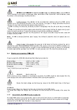
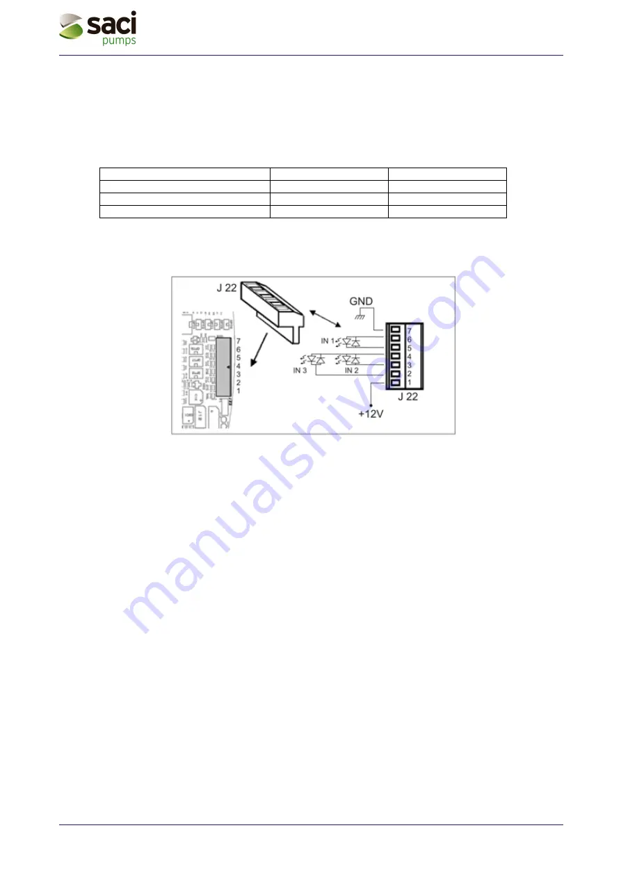
Optocoupled input contacts’ electrical features:
-
Opto coupler IN 1: Pin 5 and 6.
-
Opto coupler IN 2: Pin 2 and 4.
-
Opto coupler IN 3: Pin 3 and 4.
-
Inputs can be driven with any polarity with respect to their own earth return and they work with alternate
or direct current.
-
Correct operation is guaranteed if input voltages comply with the following requirements:
Input DC [V]
Input AC [V rms]
Trigger voltage
8
6
Max turn-off voltage
2
1,5
Max. rated voltage
48
50
Table 6: Optocoupled input contacts ratings
When input voltage is 12VDC input current is 3mA.
Figure 11: User input terminal


