Instruction manual V 2.3
17
PWM 230 - PWM 400 - PWM 400/7.5
Instruction manual
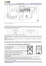
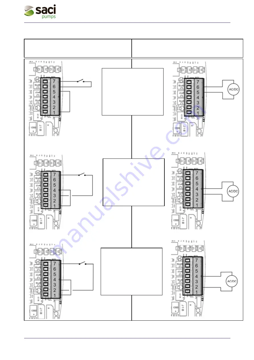
Figure 12: User inputs usage example
Jumper
Jumper
Jumper
Direct Voltage supply
(Max 48V) or
alternate Voltage
(Max 50Vrms)
Direct Voltage
supply (Max 48V) or
alternate Voltage
(Max 50Vrms)
Potential-free contacts
Potential-free contacts
Potential-free contacts
IN 1 usage example
When IN 1 is enabled, the pump is
stopped and the display reports
"F1".(e.g. IN 1 could be connected
to a float switch). for setting details
see sec. 5.1.3.9.1”I1: Setting
function of input 1 (external float).”
Driving with potential-free contacts
Driving with external Voltage
IN 3 usage example
When IN 3 is enabled the pump is
stopped and the display reports
"F3"
(e.g. it could be connected to a
safety manually reatriggerable
pressure switch) for configuration
details see sec. 5.1.3.9.3 “I3:
Setting function of input 3 (general
system enabling)”
Direct Voltage
supply (Max 48V) or
alternate Voltage
(Max 50Vrms)
IN 2 usage example
When IN 2 is enabled the set point
pressure becomes "P1". (see sec.
5.1.3.9.2 “I2: Setting function of inlet
2 (active set-point selection: “SP” or
“P1”)”)

