Page # 65
877 1st Ave. N.W. | Sioux Center, IA 51250 | Toll Free: 1.866.722.1488 | siouxautomation.com
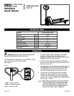
OPERATION
REPLACEMENT PARTS
READ complete manual CAREFULLY
BEFORE attempting operation.
877 1st Ave. N.W. | Sioux Center, IA 51250 | Toll Free: 1.866.722.1488 | siouxautomation.com
OPERATION
REPLACEMENT PARTS
READ complete manual CAREFULLY
BEFORE attempting operation.
•
•
•
Grease
Use SAE multi-purpose high temperature grease with extreme pressure (EP) characteristics on all areas requiring grease
lubrication.
Oil (Pump Drive)
Models equipped with the standard drive pumps will require 3.25 Qts. of
synthetic industrial gear oil with an 80W90
rating
. It is recommended to change oil after the first 500 hours or 3 months of service, whichever occurs first. Thereaf-
ter, and under normal operating conditions it is recommended to change the oil every 1000 hours or 6 months of service,
whichever occurs first.
Clean around the dipstick and oil fill holes before checking or adding oil. Drain the oil while the unit is still warm.
WARNING: Hot oil can cause severe burns. use extreme care when removing lubrication plugs and vents!
Inspect and clean magnetic drain plug for contamination or metal particles before replacing.
HyDROSTATIC OIL (HyDROSTATIC PuMP DRIvE SySTEM, AuxILIARy PuMP SySTEM)
The hydrostatic system on the 3600 Series Truck mount Mixer will require hydraulic oil having this specification:
ISO 46W HyDRAuLIC OIL
The type of oil specified is recommended for all heavy-duty hydraulic applications requiring excellent wear protection.
This oil has excellent thermal stability and oxidation life, which extends drain intervals and protects against corrosion and
varnish.
GREASING
1.
Use a hand held grease gun for all greasing.
2.
Wipe grease fittings with a clean cloth before greasing to avoid injecting dirt and grit.
3.
Replace and repair broken fittings immediately.
4.
If fittings will not take grease, remove and clean thoroughly. Also clean lubricant passageway.
Replace the fitting if necessary.
Driveshaft Assembly
All hydrostatic drive truck mount models are equipped with a driveshaft assembly that transmits power from the truck en-
gine to the hydrostatic pump drive system, Depending on the model and options specified the grease locations will vary.
Grease is required at each cross or “u”-joint found on the driveshaft. Grease is also required on the telescopic tube assem-
bly. Crosses and telescopic tube assemblies will require 1 pump every 16 hours and/or 50 loads. Refer to the diagram that
follows for typical grease locations.
IMPORTANT:
When greasing the crosses on the driveshaft al-
ways inspect the condition of the yoke and cross
assemblies for excessive play and/or movement.
Excessive play and/or movement is an indication
that the crosses may have to be serviced and/or
replaced.
FLUIDS AND LUBRICANTS
Summary of Contents for 3600 Series
Page 129: ...MAINTENANCE RECORD...
Page 130: ...MAINTENANCE RECORD...
Page 131: ...MAINTENANCE RECORD...
Page 134: ......