background image

Page # 23


877 1st Ave. N.W. | Sioux Center, IA 51250 | Toll Free: 1.866.722.1488 | siouxautomation.com

OPERATION

REPLACEMENT PARTS

READ complete manual CAREFULLY

BEFORE attempting operation.


877 1st Ave. N.W. | Sioux Center, IA 51250 | Toll Free: 1.866.722.1488 | siouxautomation.com

OPERATION

REPLACEMENT PARTS

READ complete manual CAREFULLY

BEFORE attempting operation.

CONTROLS

Page | 4  


On the User Settings Main Screen (Figure 4) there are three options – Remote Control Settings, User Settings, and 

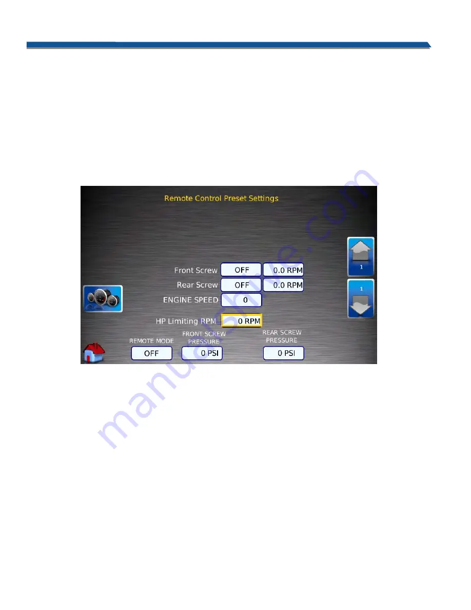
Home.  By pressing the “Remote Control Settings” icon, the display will navigate to the Remote Control Settings 

page (Figure 5).  This screen allows the operator to program a horsepower limiting auger speed.  Any changes 

made to this screen are saved upon exit.  Refer to the Machine Operation section of this manual for detailed 

descriptions of settings. 

By pressing the Up and Down icon keys, the operator can choose the auger RPM at which the mixer will operate at 

when the pressure is too high. The value will keep changing until the key is released.   


Figure 5 

By pressing the gauge key, the display will navigate back to the Operation Screen.  Pressing the Home icon will 

return the display to the Home screen. 

From the User Settings main screen (Figure 4), pressing the User Settings icon will bring up the display’s User 

Settings (Figure 6).  This screen allows the operator to choose display settings, brightness, units of measure, 

language, and a background.  Pressing the side buttons will navigate the selection box up or down to change the 

setting.  By pressing the upper left button, the display defaults are restored.  The lower left button will navigate 

back to the Home screen.  

Summary of Contents for 3600 Series

Page 1: ...x Center IA 51250 Toll Free 1 866 722 1488 siouxautomation com OPERATION REPLACEMENT PARTS READ complete manual CAREFULLY BEFORE attempting operation VM600030 REV G 04 01 21 MAXI MIXER 3600 SERIES TRU...

Page 2: ...DATED ALL ASSEMBLIES C 3 28 17 WARRANTY UPDATED WARRANTY SHEET D 9 27 17 PAGES 67 99 103 ADDED DISCHARGE CHAIN INSTALLATION ILLUSTRATION AND INSTALLATION NOTES E 10 16 20 PAGE 48 ADD NOTE FOR VM800341...

Page 3: ...oubleshooting 56 57 Mixer Set up 58 Mixer Operation 59 63 Inspection and Adjustments 64 Fluids and Lubricants 65 Conveyor Lubrication and Maintenance 66 67 Auger Maintenance 68 Hydraulic Filtration 69...

Page 4: ...ng power to any machinery used in conjunction with wagon box or when moving box Never allow anyone in near or on mixing chamber during mixing transporting or unloading of feed Thank you for choosing S...

Page 5: ...dthedischargeonthedriverssideatthebaseofthemixer Foreasyreference pleasewritethis information in the Customer Reference Information section that follows Figure 1 Serial Number Location CUSTOMER REFERE...

Page 6: ...ious injury or death This signal word is to be limited to most extreme situations typically for machine components which for functional purposes cannot be guarded warning Indicates a potentially hazar...

Page 7: ...anual and to follow them Sioux Automation Center Inc feels that a person who has not read and understood all operating and safety instructions is not qualified to operate the machine An untrained oper...

Page 8: ...from your distributor dealer parts department or factory How to install safety signs Be sure that installation area is clean and dry Decide on exact position before you remove backing paper Remove sma...

Page 9: ...iliarizeyourselfwiththevariousdecals typeofinformationprovided andtheareasthatrequireyourawareness Think SAFETY Work SAFETY DECAL A BOTH RIGHT AND LEFT SIDES DECAL B C LEFT REAR VIEW IF EQUIPPED WITH...

Page 10: ...IN DATE DATE IRST AV ENG THE INFORMATION CONTAINED IN THIS DRAWING IS THE SOLE PROPERTY OF SIOUX AUTOMATION CENTER INC ANY REPRODUCTION SPECIFIED 12 03 877 F CV DFTM GENERAL TOLERANCES E NW SIOUX CEN...

Page 11: ...l CAREFULLY BEFORE attempting operation sAFETY SIGN LOCATIONS DECAL D LOCATED BY BLOCK MANIFOLD AND PUMPS DECAL E LOCATED BY HYDRO PUMPS DECAL F LOCATED BY HYDRO PUMPS DECAL G HYDRAULIC OIL HEALTH HAZ...

Page 12: ...S SHOWN IN THE TABLE INCLUDE ALL THREE OF THE ITEMS SHOWN IN THE FIGURE IF INDIVIDUAL DECALS ARE DESIRED THE LARGER TABLE PROVIDES THOSE PART NUMBERS ITEM PART VM900275 QTY MODEL 3640 VM900276 QTY MOD...

Page 13: ...e all components are tight and that lines hoses and couplings are not damaged mAINTENANCE SAFETY Follow ALL the operating maintenance and safety information in the manual Support the machine with bloc...

Page 14: ...ntial shoes It is recommended that suitable hearing and eye protection be worn Operatormaycomeincontactwithcertainmaterialswhichmayrequirespecificsafetyequipmentrelativeto handling of such materials K...

Page 15: ...s or other obstacles Contact with overhead lines could cause serious injury or death Avoid loose gravel rocks and holes they can be dangerous for equipment operation or movement Allow for unit length...

Page 16: ...in an area away from human activity Do not park equipment where it will be exposed to livestock for long periods of time Damage and livestock injury could result Do not permit children to play on or a...

Page 17: ...may be difficult to eliminate foreign matter such as rocks stones steel wood etc However these items can place added wear on com ponents such as the mixing chamber walls auger assembly and auger kniv...

Page 18: ...0 200 225 300 3 4 165 225 290 390 400 540 7 8 170 230 420 570 650 880 1 225 300 630 850 970 1310 Torquefiguresindicated are valid for non greased or non oiled threads and heads unless otherwise specfi...

Page 19: ...auger rotates freely Remove all string twine or other entangled material 8 Check that the PTO driveline is locked to the truck s crank shaft for front mounted pumps 9 Close and secure all guards and s...

Page 20: ...feguards in the event of mechanical or hydraulic failure The following pages will step through the operation of the system and troubleshooting points The control system is powered when the truck key i...

Page 21: ...High Speed Cleanout Mode and Home Screen The right side of the display screen from top to bottom shows Day Night Mode Camera 1 Camera 2 and Camera 3 The center of the display screen shows from left t...

Page 22: ...me Screen The home screen is shown in Figure 3 From this screen the operator is able to access the means to change user settings view diagnostic screens and view and reset service intervals of the mac...

Page 23: ...icon keys the operator can choose the auger RPM at which the mixer will operate at when the pressure is too high The value will keep changing until the key is released Figure 5 By pressing the gauge k...

Page 24: ...icon is pressed the display will navigate to the Inputs Outputs Diagnostics screen Figure 7 This screen allows the operator to view stored faults diagnostics and service intervals Figure 7 By pressin...

Page 25: ...and down arrows the operator can navigate through the list of stored faults Each fault has a brief description of the fault and how to correct it at the top of the screen when that fault is selected...

Page 26: ...r status quirements if the switch is on will return the display to the Coil Pots and I Os diagnostics main screen Figure 9 Figure 10 From the Coil Pots and I Os diagnostics main screen Figure 9 pressi...

Page 27: ...ls of adjusting the conveyor chain changing the hydrostatic pump filters changing the hydraulic oil changing the auxiliary filter s and changing the pump drive gear oil It also shows how many hours ar...

Page 28: ...uits Aux 1 Pressure corresponds to the pump which controls the door up down and conveyor in out functions Aux 2 Pressure corresponds to the pump which runs the conveyor chain motor Also shown on this...

Page 29: ...l enable the High Speed Cleanout Mode Certain operating restrictions are applied in High Speed mode Refer to the Operations Section for these restrictions The Day Night icon toggles the bunk lights on...

Page 30: ...le controls the conveyor apron speed Similar to the auger controls fully counterclockwise is minimum speed while fully clockwise is maximum speed The joystick that is located on the base of the consol...

Page 31: ...t again will turn the conveyor off The switch closest to the operator on the mixer side turns the augers on and off Like the conveyor switch this is also a momentary switch press once to turn on once...

Page 32: ...ssure will be equivalent With the augers on hydraulic charge pressure will be 280 350 psi while the system pressure will be equivalent If all components of the system are functioning properly and ther...

Page 33: ...is not more feed needs to be unloaded The system will not allow the augers to shift to high speed if the pressure is over 1500 PSI If the system pressure is below 1500 PSI the operator can press the...

Page 34: ...turning and the chassis will return to a slow idle The operator can remotely engage the mixer as many times as desired during the loading and mixing process without the need to reset the display If f...

Page 35: ...3 31 Warning No Oil Temperature Detected Check wires and oil temp sensor Verify oil temperature is adequate for operation Check oil cooling system sensor and wiring Reduce operation speed and or load...

Page 36: ...and wiring Check sensor and wiring Replace as needed 522012 3 Warning Aux 2 Pressure Sensor High Voltage Check sensors and wiring Check sensor and wiring Replace as needed 522012 4 Warning Aux 2 Pres...

Page 37: ...oil temperatures of not more than 160 F If the oil temperature is higher than this components in the pumps and motors will begin to wear prematurely If the oil temperature is warm check that the oil c...

Page 38: ...re is displayed on the Operation screen of the display If the charge pressure has recovered the operator can override the warning and continue operating the mixer In some instances when the augers are...

Page 39: ...also disabled when the system pressure of either one or both of the augers is greater than 1500 psi If the operator attempts to shift the mixer into High Speed Cleanout Mode when the system pressure...

Page 40: ...to be removed from the mixer and the pumps cannot be actuated electronically a manual override button is located on the coil that will engage the pump and allow the auger to turn to unload the mixer T...

Page 41: ...or a hydraulic problem In order to accelerate the troubleshooting process to determine the cause of the failure the electronic control system has an onboard diagnostics tool to assist the operator wit...

Page 42: ...operation CONTROLS Page 23 In the Inputs Outputs Diagnostics screen Figure 19 pressing the Coil Pots I OS icon will navigate to the Coil Pots IOs Screen Figure 20 Figure 19 Figure 20 From the Coil Pot...

Page 43: ...mV As shown in Figure 10 all six of the sensors are sending information In this instance all sensors are working properly All pressure sensors g in the range of 500 4500mV which correlates to a pressu...

Page 44: ...ar Door Open indicates if the rear door is open or closed This aids in troubleshooting the rear door sensor if it become misaligned or has an electric failure Conveyor POT Signal indicates the positio...

Page 45: ...t receive a speed from either of the augers This value is factory set and cannot be changed HIGH SPEED COIL At the bottom of the screen the High Speed Cleanout coil information is shown As illustrated...

Page 46: ...Page 46 OPERATION REPLACEMENT PARTS READ complete manual CAREFULLY BEFORE attempting operation FUSE PANEL RELAY AND FUSE POSITIIONS ELECTRICAL RELAY FUSE RELAY FUSE...

Page 47: ...re controlled electronically from the control console located in the truck cab Electric Solenoid Valve Once hydraulic oil has circulated through the manifold valve and the hydraulic cooler it exits in...

Page 48: ...EED CABLE H VM700175 VM700229 VM700237 VM700278 VM800203 VM800210 VM800315 PSI SENSOR PUMP CNTRL FILTER IND CABLES J BOX SENSORS J VM700234 VM700235 VM700247 VM700248 VM800201 VM800208 VM900259 DISPLA...

Page 49: ...ND CONNECTION TO BATTERY 1 CHECK THAT HARNESS VM700281 HAS THE CAN TEE INSTALLED NEAR THE 2 ROUND DEUTSCH CONNECTOR AND RESISTOR PLUG IS IN PLACE ROUTE THE POWER GROUND AND CAN LEADS INTO THE CONTROL...

Page 50: ...ELECTRICAL KIT 21 9 6 36 23 22 25 20 ARE UP AS SHOWN MOUNT ECU TO INSIDE OF LH HYD TANK BRACKET MOUNT ECU SO THAT CONNECTION PORTS 1 4 GRAY 23 PIN AND BLACK 8 PIN CONNECT HARNESSES AS SHOWN ALL 4 ROUN...

Page 51: ...PORT JUNCTION BOX WIRING DIAGRAM SPEED SENSOR FRONT MOTOR MOTOR 2 SPEED COIL REAR MOTOR SPEED SENSOR REAR DOOR PROX SENSOR NOTES CABLES MUST BE INSTALLED IN 4 PORT JUNCTION 1 BOX IN THE NOTED POSITION...

Page 52: ...TSCH 2 PLUG WEDGE LOCK 9 60 STI700173 25 WIRE LOOM 10 6 STI700279 INSULATED TERMINAL RING 11 2 STI701245 100 AMP SLOWBLOW FUSE 12 2 STI701247 80 300 AMP FUSE BLOCK 13 240 STI702453 50 WIRE LOOM BRAID...

Page 53: ...58 BOTH VM900257 AND AND JESDTM062S OF INDEPENDENTLY OF THE JESDTM042PP007 CONNECT TO POWER SOURCE POWER STUD LOCATE FUSES IN BATTERY BOX FUSE BLOCK STI702453 TO MAKE ONE WIRE HARNESS TO CAB WRAP BOTH...

Page 54: ...r If the fluid level is higher than the maximum level fluid may overflow the reservoir and cause fluid loss after fluid warm up Check the fluid level daily and replace with recommended oil as needed T...

Page 55: ...ed hydraulically from the cab The door is opened to allow feed to come out of the mixing chamber and onto the conveyor The door can be raised to any postion up to a maximum of 32 inches 81 cm in heigh...

Page 56: ...Conveyor doesn t move Insufficient oil flow Increase oil flow at Cold temperatures pumps by speeding up motor Conveyor slats frozen Warm machine before down operating Conveyor jammed Check oil level...

Page 57: ...Page 57 OPERATION REPLACEMENT PARTS READ complete manual CAREFULLY BEFORE attempting operation TROUBLESHOOTING CONVEYOR CAP CAP RETAINING PIN...

Page 58: ...ened properly See Torque Spec Check the augers Remove all string twine or other entangled material Check that no hoses are pinched rubbing or being crimped Re align as required Check for oil leaks Sto...

Page 59: ...n on the drive train and mixer is greatly increased The high speed setting for the auger motors can be used for final cleanout when there is less than 2000 lbs of the load remaining MIXING SPEED hay R...

Page 60: ...tional cutting will take place during mixing so be careful not to over cut The type of mix required varies from one operation to the other and therefore mixing times and procedures will vary as well T...

Page 61: ...other ingredients Adjustments When processing materials there may be spillage over the side of the mixer The following steps are to help reduce spillage Reduce load size Reduce mixer RPM Be sure mixer...

Page 62: ...desirable length the loading of remaining ingredients can begin The sequence of loading materials will depend on the loading methods and their location relative to the mixer but a typical loading sequ...

Page 63: ...l liners are available for installation when mixing course materials to extend mixing chamber life span REAR DOOR DISCHARGE CONFIGURATIONS The rear discharge door is controlled hydraulically from the...

Page 64: ...damaged or missing hardware Wheel Bolts must be kept properly torqued Damage to the rim may occur if wheel bolts are not checked frequently Freezing Weather Snow can accumulate in mixer if stored out...

Page 65: ...recommended for all heavy duty hydraulic applications requiring excellent wear protection This oil has excellent thermal stability and oxidation life which extends drain intervals and protects against...

Page 66: ...aft bearings These bearings will require 1 pump every 16 hours or 50 loads Grease fitting locations are shown in the diagrams that follow Magnet Chute Assembly If equipped On machines equipped with th...

Page 67: ...g anchor bolts c Slide or tap housing to the required position Use adjusting bolt to move housing if required d Repeat with other housing Important Always move both ends of the shaft the same amount t...

Page 68: ...stop before servicing adjusting repairing or unplugging 3 Install new knives and tighten mounting bolts to their specified torque 4 Keep knives in good condition Replace if chipped dull or damaged in...

Page 69: ...0210 BRAND NAME PART NUMBER FORCE AMERICA F5068 10C NAPA 1759 ZINGA SE10 SIOUX AUTOMATION HYDFAFSF510210 Auxiliary Circuit Filter Located on the return line near the oil cooler is a hydraulic oil filt...

Page 70: ...quipped with remote charge pump filters It is critical that these filters are changed on a regular basis to keep the system running normal The charge filters 2 per unit located at the front of the tru...

Page 71: ...r ports and feeling aroound on the bottom of the reservoir If excess metal shavings are found it could be an indicator of pump or motor damage g With inspection complete reinstall the suction strainer...

Page 72: ...its connec tions Should a hydraulic hose and or adapter require service contact your local SAC Dealer or Distributor Always give your Dealer the Model Number and Serial Number of you Maxi Mixer With t...

Page 73: ...y Note the hy draulic oil flow directions in and out of the cooling system It is important to maintain this flow configuration should any of the circuits be disconnected for service Care must be taken...

Page 74: ...DRAULIC HOSE 65 2 2 2 2 2 VM700214 HYDRAULIC HOSE VM900253 1 QTY 3675 FEPTO KIT VM900253 2 QTY 3690 FEPTO KIT VM900253 3 QTY 36100 FEPTO KIT VM900253 4 QTY 36125 DAIRY KIT VM900253 5 QTY 36125 FDLT KI...

Page 75: ...0224 1 HYDRAULIC HOSE 0 1 0 0 0 VM700224 2 HYDRAULIC HOSE 0 0 1 1 1 VM700224 3 HYDRAULIC HOSE 85 1 1 1 1 1 VM700225 HYDRAULIC HOSE 86 1 1 1 1 1 VM700226 HYDRAULIC HOSE 87 1 0 0 0 0 VM700227 1 HYDRAULI...

Page 76: ...PRESSURE PORT F REMOTE FILTER OUT TO FILTER REMOTE FILTER PORT E IN FROM FILTER CASE DRAIN PORT L2 CHARGE PRESSURE GAUGE PORT M3 PORT A HIGH PRESSURE M4 PUMP INLET HIGH PRESSURE PORT B PUMP AND MOTOR...

Page 77: ...LINES HYDRAULIC TANK ASSEMBLY HYDRO INLET 2 SPEED VALVE 62 16 62 10 16 62 62 NOTE INSTALL HYD6815 6 6 PRIOR TO MOUNTING PUMPS 10 HYDRO HIGH PRESSURE SUCTION LINE PLUMBING OUTLET TO TANK OUTLET TO TAN...

Page 78: ...3690 36100 TO MOTOR CASE FLUSH LINE PUMP 2 59 58 14 14 MOTOR 2 ENSURE THAT ARROWS ON CASE FLUSH VALVES POINT TOWARDS MOTORS FOR PROPER FLOW 101 4 48 TO MOTOR CASE FLUSH LINE PUMP 1 TO 2 SPEED VALVE N...

Page 79: ...8 60 83 NOTE 91 42 38 53 BLOCK 1 PORT B2 TO LOOP FLUSH BLOCK 2 PORT A1 TO LOOP FLUSH BLOCK 1 PORT A2 TO LOOP FLUSH BLOCK 2 PORT B1 TO LOOP FLUSH REAR MOTOR 2 MOTOR 1 36125 DAIRY MOTOR CASE FLUSH 2 SPE...

Page 80: ...2 BLOCK 1 PORT B2 42 53 37 83 91 37 BLOCK 1 PORT A2 TO LOOP FLUSH BLOCK 2 PORT A1 TO LOOP FLUSH BLOCK 2 PORT B1 TO LOOP FLUSH TO LOOP FLUSH 36125 FEEDLOT MOTOR CASE FLUSH 2 SPEED PLUMBING 69 13 32 78...

Page 81: ...PORT A MOTOR 1 RETURN PORT B PUMP 1 PRESSURE PORT A PUMP 1 PRESSURE PORT A PUMP 2 RETURN LOOP FLUSH VALVE BLOCK PLUMBING 58 56 4 101 59 48 100 PORT B 47 6 34 62 35 34 62 19 PUMP 2 35 39 17 65 65 26 44...

Page 82: ...APTER 30 1 1 1 1 1 HYDE810 BARB ADAPTER 31 8 8 8 8 8 HYDFF6400 16 16 CONNECTOR ADPATER 32 4 0 0 0 0 HYDFF6842 16 12 SPLIT FLANGE ADAPTER 0 4 4 0 4 HYDFF6842 16 16 SPLIT FLANGE ADAPTER 0 0 0 4 0 HYDFF6...

Page 83: ...0 0 0 VM700227 1 HYDRAULIC HOSE 0 1 0 0 0 VM700227 2 HYDRAULIC HOSE 0 0 1 1 1 VM700227 3 HYDRAULIC HOSE 87 1 0 0 0 0 VM700228 1 HYDRAULIC HOSE 0 1 0 0 0 VM700228 2 HYDRAULIC HOSE 0 0 1 1 1 VM700228 3...

Page 84: ...TER OUT TO FILTER PORT F REMOTE FILTER HIGH PRESSURE GAUGE PORT MB PORT A HIGH PRESSURE M4 PUMP INLET HIGH PRESSURE PORT B CASE DRAIN PORT L4 HIGH PRESSURE GAUGE PORT MB CASE FLUSH OUTLET MOTOR INLET...

Page 85: ...50 47 49 41 54 NOTE HOSE MAY BE REQUIRED TO BE SHORTENED ALLOW FLEXIBILITY IN TANK SUPPLY LINE 54 TO HYDRO CASE DRAIN MOTOR CASE FLUSH RETURN 71 11 48 11 48 20 63 94 2 SPEED VALVE DRAIN FROM PORT 1 H...

Page 86: ...P FLUSH BLOCK 1 PORT B1 TO LOOP FLUSH BLOCK 1 PORT A2 TO LOOP FLUSH BLOCK 2 TO LOOP FLUSH BLOCK 2 53 93 93 CONNECT TO HYD1456 175 FLOW CONTROL HYDRO HIGH PRESSURE CASE DRAIN CASE FLUSH PLUMBING NOTE S...

Page 87: ...24 64 64 24 65 14 10 13 26 14 10 13 27 18 71 58 59 104 45 4 97 97 19 REAR MOTOR 2 FRONT MOTOR 1 TO TANK FLUSH LINE PUMP 1 TO MOTOR CASE FLUSH LINE PUMP 2 TO 2 SPEED VALVE PORT 2 TO 2 SPEED VALVE 3675...

Page 88: ...ING MOTOR CASE FLUSH SEE SHEET 5 FOR CASE FLUSH VALVE NOTE PLUMBING AND MOUNTING 36125 DAIRY MOTOR HIGH PRESSURE HOSE PLUMBING MOUNTING NOTE MOUNT ADAPTER RINGS TO FLOOR OF MIXER AND BOLT MOTORS TO AD...

Page 89: ...71 18 29 67 12 28 64 25 29 76 70 12 28 25 2 SPEED PLUMBING MOTOR CASE FLUSH 36125 FEEDLOT PLUMBING AND MOUNTING SEE SHEET 5 FOR CASE FLUSH VALVE NOTE 36125 FEEDLOT MOTOR HIGH PRESSURE HOSE PLUMBING M...

Page 90: ...RT R MOTOR 1 PORT A MOTOR 2 PORT A MOTOR 2 PORT R PUMP 1 PORT A PUMP 1 PORT B PUMP 2 PORT B PUMP 2 PORT A 31 NOTE MOUNT VALVES AS FAR TO CURBSIDE AS POSSIBLE TO AVOID INTERFERENCE WITH CONVEYOR SLIDE...

Page 91: ...HARNESS 3 BANK 68 0 2 WSH14LOCK 1 4 LOCK WASHER 69 3 3 WSH38LOCK 3 8 LOCK WASHER ITEM VM900254 1 QTY STANDARD VM900254 2 QTY STANDARD REAR DOOR PART DESCRIPTION 1 0 2 BLT14X34NC 1 4X3 4 BOLT 2 3 3 BL...

Page 92: ...AR 005 1 10 SHEET OF 2 5 XX 03 XXX THIRD ANGLE DATE HYDRAULIC TANK ASSEMBLY FROM OIL 27 59 6 31 COOLER OUTLET ENG D C B A B C D 1 2 3 4 5 6 7 8 8 7 6 5 4 3 2 A 1 VM900254 DWG NO DO NOT SCALE DRAWING E...

Page 93: ...THE SOLE PROPERTY OF SIOUX AUTOMATION CENTER INC ANY REPRODUCTION GENERAL TOLERANCES SIZE E NW SIOUX CENTER IA 51250 8 13 IRST AV 877 F SPECIFIED DATE DFTM JR DIMENSIONS ARE IN INCHES TOLERANCES UNLES...

Page 94: ...13 IRST AV 877 F SPECIFIED DATE DFTM JR DIMENSIONS ARE IN INCHES TOLERANCES UNLESS SAC MATERIAL SCALE DWG NO B REV KIT HYD AUX VM 36XX FEPTO VM900254 E AS NOTED SIOUX AUTOMATION CENTER INC 1 ANGULAR...

Page 95: ...NC 3 8 LOCK NUT 29 2 2 NUT38NC 3 8 NUT 30 4 4 NUT516NC 5 16 NUT 31 100 100 SPCABLETIEHVY 175 CABLE TIE 32 1 1 VM100448 VALVE BRACE 33 0 1 VM100673 REAR DOOR SENSOR TAB 34 1 1 VM100681 TANK MOUNT 35 1...

Page 96: ...e manual CAREFULLY VM900361 TRUCK REPTO AUX HYDRAULIC ASSEMBLY HYD VALVE MOUNTING HYD TANK AND COOLER PLUMBING NOTE USE CLOSER HOLE SPACING FOR 3 BANK VALVE 2 35 63 4 30 3 62 55 51 28 39 59 36 17 9 43...

Page 97: ...G NOTE ENSURE UNUSED PORTS IN AUXILAIRY PUMPS ARE PLUGGED AND FITTINGS ARE TIGHT IN PRESSURE PORT 20 38 10 14 53 55 16 INSTALL VM800203 PRESSURE TRANSDUCER FROM VM900319 KIT 59 18 53 21 52 17 9 39 IN...

Page 98: ...D03 VALVE PLUMBING NOTE FOR UNITS EQUIPPED WITH NO REAR DOOR PLUG PORTS OF VALVE 3 INSTEAD OF VALVE 4 12 11 39 37 7 45 12 18 TO CONVEYOR MOTOR 18 FRONT DOOR ROD END BUTT END DISCHARGE SLIDE REAR DOOR...

Page 99: ...9 11 11 11 WSH38FLAT 3 8 FLAT WASHER 40 11 11 11 WSH38LOCK 3 8 LOCK WASHER SALES PACKAGES ITEM QTY PART DESCRIPTION CHASSIS A 1 CHASSIS XX CAB TO TRUNION TRUCK SCALE PACKAGES B 1 VM900234 DS SCALE KIT...

Page 100: ...700135 BOLTS TO THESE BRACKETS 4 COOLER IS PART OF 17 HYDRAULIC TANK MUST BE INSTALLED NOTE ASSEMBLY VM700137 PRIOR TO INSTALLING LADDER BUNK LIGHT E 35 19 30 26 20 29 28 40 39 15 7 37 6 13 35 4 11 39...

Page 101: ...8 36100 36125 FEPTO 8 177 263 36100 36125 REPTO 14 193 279 NOTE REPTO DIMENSION IS TO HYD TANK 36 SERIES TRUCK MOUNTING DIMENSIONS X Y Z 3675 FEPTO 8 156 241 3675 REPTO 14 172 257 3690 FEPTO 8 169 252...

Page 102: ...NT PARTS READ complete manual CAREFULLY BEFORE attempting operation MACHINE MOUNTS Note Mounting configurations may differ due to chassis and frame differences See your SAC dealer for details if mount...

Page 103: ...T 1 VM700061 96 DIA DOOR WELDMENT 1 VM700062 102 DIA DOOR WELDMENT 3 2 VM100176 OUTER DOOR TRACK 4 2 VM100174 1 8 DOOR SPACER 5 2 VM100175 1 4 DOOR SPACER 6 2 SPHPN316 3 16 PIN CLIP 7 1 VM100185 VIEWI...

Page 104: ...TRICTOR BLADE 4 1 VM800055 RESTRICTOR BLADE PIN RESTRICTOR BLADE ITEM QTY PART DESCRIPTION 1 2 SPHPN332 PIN HAIR 3 32 2 1 SPPP12X212 PIN PICKER 1 2 2 1 2 3 1 VM100640 BLADE RSTRCTR 63 36s 4 1 VM800055...

Page 105: ...COVER 5 6 WSH38LOCK 3 8 LOCK WASHER VM700260 90 DIAMETER AUGER FITS MODEL 3675 1 3 4 2 5 ITEM QTY PART DESCRIPTION 1 1 VM700261 96 DIA AUGER 2 6 BLT38X112NC 3 8X1 1 2 BOLT 3 1 VM100188 ANGLE BLADE 4 1...

Page 106: ...SH38LOCK 3 8 LOCK WASHER VM700262 102 DIAMETER AUGER FITS MODEL 36100 AUGER ASSEMBLIES 3 1 4 2 5 ITEM QTY PART DESCRIPTION 1 1 VM700263 102 DIA AUGER MS83 2 6 BLT38X112NC 3 8X1 1 2 BOLT 3 1 VM100188 A...

Page 107: ...D AT 19 TO 31 INCHES FROM THE FLOOR OF THE MIXER REFER TO FIGURES A AND B STEP 5 PLACE SHIMS IN BETWEEN THE OD OF THE FLANGES AND THE ID OF THE TUBE IN AT LEAST 3 LOCATIONS REFER TO FIGURE B THIS WILL...

Page 108: ...CKNC 3 8 LOCK NUT 4 15 21 21 NUT58LOCKNC 5 8 LOCK NUT 5 5 7 7 SAC60548 UNIVERSAL KNIFE 6 5 7 7 SAC60549 KNIFE SUPPORT 7 15 21 21 WSH58FLATG8 G8 5 8 FLAT WASHER PART DESCRIPTION APPLICABLE MODEL S VM90...

Page 109: ...8 8 ADAPTER 4 1 1 1 HYD6602 8 8 8 TEE ADAPTER 5 2 2 2 HYD6801 8 10 ELBOW ADAPTER 6 1 1 1 HYD6801 8 8 ELBOW ADAPTER 7 2 2 2 HYDS7115 COUPLER TIP 8 16 16 16 NUT38NC 3 8 NUT 9 4 4 4 SPHPN316 3 16 HAIR P...

Page 110: ..._________________________________________ _____________________________________________________________________________________________ ________________________________________________________________...

Page 111: ...ENSION 22 1 VM100356 COUPLING COVER 23 1 VM100357 FLAP RETAINER 24 1 VM100363 DEFLECTOR FLAP 25 2 VM100364 BEARING 26 1 VM100365 BOTTOM APRON GUARD 27 1 VM100786 END DISCHARGE SHIELD ITEM QTY PART DES...

Page 112: ...48 37 3 5 12 5 5 28 27 29 30 12 5 5 3 12 5 5 33 23 24 31 36 19 48 49 12 49 48 5 49 48 3 48 49 12 48 49 12 48 49 12 48 49 12 48 49 12 48 49 12 48 49 12 34 BOTTOM SIDE BOTTOM OF TUBE IS ALIGNED WITH BOT...

Page 113: ...PART DESCRIPTION 1 2 BRGUCF20720 BEARING 2 2 KEY516X112 5 16X1 1 2 KEY 3 1 VM700316 DRIVE SHAFT 4 2 VM800368 SPROCKET VM900160 ITEM QTY PART DESCRIPTION 1 2 BRGUCF206 18 BEARING 2 2 KEY14X112 1 4X1 1...

Page 114: ...BULKHEAD ADAPTER 2 1 1 1 VM700145 HYDRAULIC HOSE 3 1 1 1 VM700146 HYDRAULIC HOSE 4 1 1 1 VM700162 HYDRAULIC HOSE 5 1 1 1 VM700276 HYDRAULIC HOSE 6 1 1 1 VM700277 HYDRAULIC HOSE 7 1 1 1 VM900345 DOGLEG...

Page 115: ...T 26 1 VM100404 BOTTOM APRON GUARD ITEM QTY PART DESCRIPTION 28 1 VM100785 FRONT DISCHARGE SHIELD 29 1 VM100786 END DISCHARGE SHIELD 30 1 VM100787 CORNER SHIELD SUPPORT 31 1 VM100796 APRON FLOOR 32 1...

Page 116: ...6 14 13 48 47 19 53 52 12 53 12 3 51 10 1 9 49 7 31 44 8 45 52 10 2 12 52 53 3 12 52 53 5 12 53 52 12 3 20 21 26 36 26 27 39 2 53 23 24 26 53 52 12 3 52 53 3 12 41 53 52 12 5 40 BOTTOM SIDE BOTTOM OF...

Page 117: ...RIAGE BOLT 4 10 NUT14NC 1 4 NUT 5 10 NUT38NC 3 8 NUT 6 5 NUT516NC 5 16 NUT 7 1 SPMAGNET2400 MAGNET 8 1 VM100169 BELT RETAINER 9 1 VM100265 DEFLECTOR BELT 10 1 VM100302 BOTTOM RUBBER DEFLECTOR 11 1 VM7...

Page 118: ..._________________________________________ _____________________________________________________________________________________________ ________________________________________________________________...

Page 119: ...10 2 KN174724 RT ANGLE CONNECTOR 11 2 MON104325 BUNK LIGHT BRACKET 12 2 NUT516NC 5 16 NUT 13 3 SPB14318 2 5 GROMMET 14 1 SPB15049 TRIPLE CONNECTOR PLUG 15 2 SPB42149 RT ANGLE CONNECTOR 16 4 SPB42618 4...

Page 120: ...TS 13 1 VM700109 FEPTO BUMPER 14 60 WRM8CHANNEL BUMPER CHANNEL 15 10 WSH34LOCK 3 4 LOCK WASHER 16 4 WSH58LOCK 5 8 LOCK WASHER VM900205 1 8 15 2 5 3 13 3 8 9 11 11 15 5 14 7 16 12 4 12 14 10 VM900203 V...

Page 121: ...C 3 4X2 1 2 BOLT 3 1 BLT38X114NC 3 8X1 1 4 BOLT 4 6 NUT34NC 3 4 NUT 5 1 NUT38NC 3 8 NUT 6 1 SAC30153 1 1 2 PIPE X 48 7 1 SAC56071 ROLLER ASSEMBLY 8 1 SAC56073 BUMPER 9 4 WSH12FLAT 1 2 FLAT WASHER 10 6...

Page 122: ...attempting operation 5 3 1 5 2 4 6 1 ITEM QTY PART DESCRIPTION 1 2 PTO4 2 669 1550 SERIES YOKE 2 1 PTO4 3 1241KX SLIP SLEEVE YOKE 3 1 PTO4 28 307 1 38 YOKE 4 1 PTO4 40 761 SLIP SHAFT YOKE 5 2 PTO5 155...

Page 123: ...9 30 SPCABLETIEMED CABLE TIE 10 1 VM100247 INDICATOR BRACKET 11 12 WSH14LOCK 1 4 LOCK WASHER ITEM QTY PART DESCRIPTION 1 8 BLT14X34NC 1 4X3 4 BOLT 2 3 HYDHK1313 WIRE CLAMP 3 8 NUT14NC 1 4 NUT 4 1 SCA1...

Page 124: ...MOTE POCLAIN TRK MACK ITEM VM900269 1 QTY VM900269 2 QTY VM900269 3 QTY PART DESCRIPTION 1 1 1 1 MON800208 RAM SYSTEM MANUAL 2 1 1 1 MON600209 RAM INSTALLATION MANUAL 3 1 1 1 MON901031 REMOTE CONTROL...

Page 125: ...NDING ON CAMERA MOUNTING LOCATIONS VM800215 20 VM800216 65 ITEM VM900271 1 QTY 1 CAMERA VM900271 2 QTY 2 CAMERA VM900271 3 QTY 3 CAMERA PART DESCRIPTION 1 4 4 4 BLT14X34NC 1 4X3 4 BOLT 2 2 2 2 NUT14NC...

Page 126: ...FITS 3675 VM900181 11 QTY FITS 3690 VM900181 12 QTY FITS 36100 36125 1 BEL12X124PLY 12 BELTING 546 600 648 MON800441 8 BELTING 546 600 648 2 BLT38X112NC 3 8X1 1 2 BOLT 44 49 53 44 49 53 3 BLT38X134NC...

Page 127: ...102 102 C Frame to Tub Height 80 72 73 91 D Mixing Chamber Length 222 244 252 252 E Overall Length 257 275 285 285 F Cab to Trunnion w Front Engine PTO 156 169 177 177 G Side Discharge transport width...

Page 128: ..._________________________________________ _____________________________________________________________________________________________ ________________________________________________________________...

Page 129: ...MAINTENANCE RECORD...

Page 130: ...MAINTENANCE RECORD...

Page 131: ...MAINTENANCE RECORD...

Page 132: ...labor done at the SAC factory or SAC authorized dealer ONLY SAC will pay the common carrier freight expense of parts to and from the owner Faster freight service is available with the owner paying the...

Page 133: ...hen any party other than SAC performs the replacement or repair of parts claimed to be defective nor shall this warranty apply to an SAC product upon which any alterations or repairs other than normal...

Page 134: ......

Reviews: