Installation, operating and maintenance manual SKIT/S-DEB
3rd print version
page 94
15 – Annex
RWO GmbH
●
Marine Water Technology
●
Bremen
●
Germany
Issue 2014-04-10
15
Annex
15.1
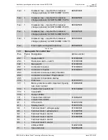
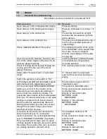
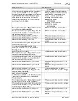
Checklist for commissioning
The middle column is provided for a checkmark "OK".
Start procedure
OK Remarks
Open valve(s) in the compressed air supply.
Pressure 6-8 bar.
Open valve(s) in the flushing water supply.
Pressure of between 1 and max. 1.5
bar.
Open valve(s) in the suction line
The suction line must be air-tight
because the oil separator operates
with a vacuum.
Open valve(s) in the outboard line.
The pump is a displacement pump; it
must not be operated upstream of
closed fittings.
Check rotational direction of the pump
The rotational direction of the pump
is "CLOCKWISE" when viewed from
the motor. Incorrect rotational
direction bears danger of the pump
running dry!
Open the tap of the adsorber housing cover
until the adsorber is filled with water
Cut off the rubber nipples of the caps on all
pressure gauge housings
so that pressure compensation
becomes possible
Check if cooling air can escape through the
venting grid of the fan cap of the motor
without hindrance
This ensures proper motor cooling
Select either "manual mode" or "automatic
mode"
In "manual mode" no automatic
switch-off occurs when the bilge is
empty
Switch the system's main switch to "On"
a) The bilge level LED only illuminates in green
when the level in the bilge is high enough
Prerequisite for system start in
"automatic mode",
b) The control light "RED-OILDISCHARGE"
lights up in red (oil to the collector tank),
because the sensor electrode indicates air
and oil (both non-conductive media). The
pneumatic piston valves at the flushing water
inlet (pos. 15) and oil outlet (pos. 4) are open
(voltage is applied to both solenoid valve)
and the system is automatically filled with
flushing water and at the same time vented
through the oil outlet. The pump remains
switched off in this process
The system is filled with water
Pump and heater are switched off
during that time.
Display in automatic mode:
BETRIEB AUTO
DISCHARGE
Display in manual mode:
BETRIEB HAND
DISCHARGE
c) As soon as the water level reaches the
sensor electrode (pos. 9) (conductive
medium detected), the control light switches
over to “ORANGE-FLUSHING” (backflash).
The pneumatic piston valve (pos. 5) opens
(voltage applied at solenoid valve) and with a
time delay the oil outlet valve (pos. 4) closes
(no voltage applied to solenoid valve).
The backflush starts (8 to 50
seconds)
Pump and electric heater are now
switched off.
Display in automatic mode:
BETRIEB AUTO
FLUSHING
Display in manual mode:
BETRIEB HAND


