Installation, operating and maintenance manual SKIT/S-DEB
3rd print version
page 44
8 – Installation plan
RWO GmbH
●
Marine Water Technology
●
Bremen
●
Germany
Issue 2014-04-10
8
I
nst
al
l
at
i
on
pl
an
8.1
P&ID (pipeline and instrument diagram)
See documentation
8.2
Installation scheme – suggestion
Position list
Pos. Designation
Flange connections
4
Oil discharge valve
(outlet)
R-thread or DIN 2633 PN16
5
Flush valve (outlet)
R-thread or DIN 2633 PN16
21
Sieve basket
(optional)
R-thread or DIN 2633 PN16
22
Suction line from
bilge (bilge water
tank)
23B/
55B
Back to bilge, bilge
water tank
24
Outboard valve
(optional)
55A Overboard line
R-thread or DIN 2633 PN16
Tab. 12 Component overview, installation scheme
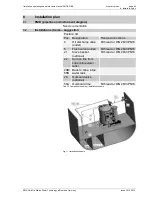
Fig. 11 Installation scheme


