A4
US
US
A4
US
A4
A4
US
37
Redefining Flow Control
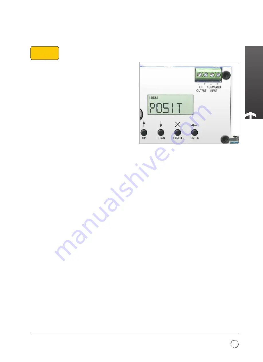
6. CALIbRATe CoMMAnd sIgnAL ZeRo seTpoInT
After the open/close limit is set the 4 to 20 mA signal is
automatically calibrated to those positions. The 4 mA input
command will send you to CLOSED LIMIT, the 20 mA and will
send you to OPEN LIMIT. However to calibrate to field signal
follow page 38.
bAsIC seTup
The CMA proportional controller enables the actuator
to automatically position a valve or actuated device in
proportion to an analogue mA current. A signal derived from
the actuator position feedback is compared with a signal
proportional to the input signal. The difference (error) is used
to energize the motor and drive the output to the required
position to cancel the error.
Unwanted frequent operation can be prevented by
adjustment of the deadband.
noTe: The 4 mA command signal is automatically
referenced to the fully closed limit position. If necessary
reverse the limits of travel to achieve the desired
command signal response.
basic setup
STEP 1
SELECT LOCAL
OPERATION
STEP 2
SET OUTPUT
TORQUE/THRUST
STEP 4
SET CLOSE LIMIT
OF TRAVEL
STEP 5
SET OPEN LIMIT
OF TRAVEL
STEP 6
CALIBRATE COMMAND
SIGNAL ZERO SETPOINT
STEP 7
CALIBRATE COMMAND
SIGNAL SPAN SETPOINT
STEP 3
SELECT ACTION AT END
OF TRAVEL ( LIMIT OR FORCE)
STEP 8
DEADBAND
Fig. 37.1


