28
FA ROTEX A1 BGe - 02/2014
6
x
Control unit
6.5.2 Changing the flue gas temperature sensor
The flue gas temperature sensor is mounted in the flue gas duct
of the heat generator using a packing gland and connected to the
sensor cable using a floating plug connection.
1. Remove the sound insulation hood and the boiler panelling.
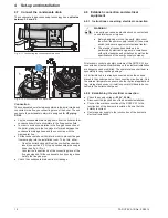
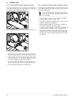
Release the plug connection on the sensor cable (fig. 6-12).
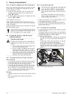
2. Unscrew the sensor sleeve from the flue gas duct by using an
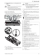
SW 24 wrench (fig. 6-13). The flue gas temperature sensor
can only be completely changed with the sleeve.
3. Screw in the new sensor sleeve into the flue gas duct and
tighten it carefully using the SW 24 wrench (plastic thread!).
4. Restore the plug connection on the sensor cable.
6.5.3 Changing the storage tank temperature sensor
The storage tank temperature sensor is connected directly to the
connection terminals 9 and 10 of the 12-pin sensor connector
J8
in the boiler control panel.
1. Open the boiler control panel and pull connector
J8
off the
circuit board (see section 6.3, steps 1 to 4).
2. Pull out the storage tank temperature sensor from the sensor
immersion sleeve at the storage tank.
3. Bend the pressing springs on the new sensor and push the
new sensor into the sensor immersion sleeve.
The insertion depth is marked on the ROTEX storage tank by
a coloured marking, depending on the storage tank type.
4. Clamp the sensor cable on the connector of the connection
terminals 9 and 10 of the 12-pin sensor connector
J8
, plug in
the connector on the switchboard PCB and close the boiler
control panel.
Fig. 6-12 Release the plug connection for the flue gas temperature sen-
sor
Fig. 6-13 Unscrew the flue gas temperature sensor
For further information on fitting the storage tempera-
ture sensor see: "Storage temperature sensor" installa-
tion instructions.


