7
x
Gas burner
FA ROTEX A1 BGe - 02/2014
35
7.3.2 Checking and setting the burner
The burner is configured for a certain type of gas at the factory.
The preset gas type and the designated gas inlet pressure are in-
dicated on the yellow sticker placed on the burner housing.
Testing the burner output using the flue gas analysis unit in the
operating mode "Emission Measurement" (see chapter 15.2)
Ɣ
at "Full Load"
Ɣ
at "Base Load"
Using this operating mode you can activate the parameters set in
the parameter level "Expert Config", "Full Load" (parameter "Fan
Max") and the "Base Load" (parameter "Fan Min"). Within the
permissible limit values (see tab. 7-2 to tab. 7-3), these settings
can be adjusted individually to the respective system require-
ments.
Auxiliary resources
– Flue gas analysis device.
– Pressure meter for measuring gas pressure.
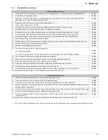
Tests and settings (observe the sequence)
1. Inspect the pre-settings, so that the burner is set to the correct
gas type and the correct gas inlet pressure.
If the test gas indication on the yellow sticker on the burner
housing varies from the test gas associated to the available
gas type or if the stated value deviates from the permissible
gas inlet pressure, the burner must be converted to the local
conditions (see section 7.3.3 to 7.3.6).
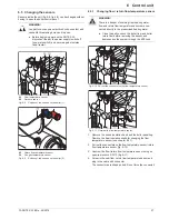
2. Turn the screw in the gas inlet pressure measuring
connection (fig. 7-3, item 9) anticlockwise by half a turn and
push up the measuring hose of the pressure meter.
3. Open the gas stopcock.
4. Measure the gas inlet pressure (idle pressure) and compare
it with the target value (see tab. 12-3). Leave the measuring
instrument connected.
– If the gas inlet pressure (resting pressure) is outside the
set value range: Inform your gas supply company or
check the pressure regulator (for liquid gas).
5. Open the heating valves.
6. Switch on ROTEX A1 with main switch.
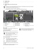
7. Switch on the operating mode "Emission Measurement" for
Full Load.
8. Connect up the flue gas analysis unit.
9. Check flow pressure.
– The gas intake flow pressure is not allowed to drop signif-
icantly below the idle pressure less the pressure drop in
the corrugated gas connection hose (up to 5 mbar for
42 kW burner load). If the flow pressure is too low, the
burner output also drops.
10. If the measured flue gas values do not change anymore (for
the soonest
3 min
after the start of the burner), measure the
CO
2
-content and the O
2
-content. Compare the measured
values with the specified setting values (see section 7.3.1).
11. If the CO
2
concentration is outside
±
0.2 % or the O
2
concentration is outside
±
0.3 % of the set target values:
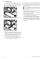
Readjust burner
using the adjusting screw for the gas/air
mixture (fig. 7-3, item 11) :
– Left turn (counter clockwise)
Î
more gas: O
2
↓
, CO
2
↑.
– Right turn (clockwise)
Î
less gas: O
2
↑
, CO
2
↓.
12. Set operating mode "Emission Measurement" to Base Load.
13. If the measured flue gas values do not change anymore (for
the soonest
2 min
after energy change), measure the CO
2
-
content and O
2
-content. Compare the measured values with
the specified setting values (see section 7.3.1).
14. If the CO
2
concentration is outside
±
0.2 % or the O
2
concentration is outside
±
0.3 % of the set target values or
the burner whistles:
Readjust the burner
using the adjusting
screw for the gas pressure controller (fig. 7-3, item 12)
(see section 7.3.6):
– Left turn (counter clockwise)
Î
less gas outlet
pressure: O
2
↑
, CO
2
↓.
– Right turn (clockwise)
Î
more gas outlet
pressure: O
2
↓
, CO
2
↑.
15. Set the operating mode "Emission Measurement" to Full Load
and re-check the combustion values.
– The values adjust according to the specifications (com-
pare step 8)
Î
adjustment procedure is finished.
– The values adjust not according to the specifications
Î
repeat the steps 8-14.
16. Enter all changes to the performance set values on the setting
type plate at the top of the boiler control panel (fig. 3-1,
item 23) and in the operating manual.
7.3.3 Carrying out the basic setting on the burner.
If the burner does not start, even with the power and gas supply
properly connected and with the flue gas path free, a new burner
basic setting must be carried out see section.
Basic setting
1. Screw in the adjusting screw for the gas/air mixture (fig. 7-3,
item 11) clockwise up to the stop (do not tighten).
2. Open the adjusting screw for the gas/air mixture according to
tab. 7-4 counter clockwise:
*
Liquefied petroleum gas design (F)
3. Restart the burner.
4. If the burner does not start, open the adjusting screw for
gas/air mixture further by
2 more turns
and restart the
burner.
If the burner does not start, even with the power and
gas supply properly connected and with the flue gas
path free, a new burner basic setting must be carried
out (see section 7.3.3).
Gas type
Associated test
gas
Number of rotations
A1 BG 25(F)-e A1 BG 40(F)-e
Natural gas
E/H
G20
8
9
Natural gas
LL/L
G25
10
11
Propane*
G31
9
11
Butane*
G30
7
9
Tab. 7-4 Number of rotations for adjusting the gas/air mixture
After the basic settings of the burner have been carried
out, the burner must be checked and fine adjustment
must be carried out (see section 7.3.7).


