background image

36

FA ROTEX A1 BGe - 02/2014

x

 Gas burner

7.3.4 Resetting the gas type

The burner is factory set to the gas type indicated on the yellow 
sticker on the burner housing or on the settings type plate 


(fig. 7-5).

Resetting from natural gas E/H to natural gas LL/L

1. Open adjusting screw for gas/air mixture (fig. 7-3, item 11) 

2 rotations

 anticlockwise.

2. Set burner (see section 7.3.2).

3. A gas type changeover and the adjusted thermal load must 

be entered on the settings type plate and in the operating 
manual and confirmed with signature.

4. Place the device sticker for LL/L gas setting (in scope of 

supply) on the fan housing of the burner.

Resetting from Liquid petroleum gas to natural gas

1. Switch off the ROTEX A1 and secure against restart.

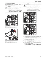
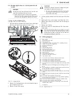
2. Remove the plug from the gas regulation block (fig. 7-6, 

step 1).

3. Disconnect the air intake pressure hose (fig. 7-3, item 21) 

from the safety gas control block (fig. 7-2, item 3).

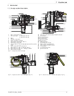
4. Unscrew the Venturi nozzle with the safety gas control block 

from the burner blower (fig. 7-6 step 2) and remove it 


(fig. 7-7).

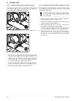
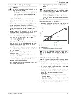
5. Unscrew and remove the 3 bolts that bolt down the venturi 

nozzle to the safety gas control block (fig. 7-8, step 1).

6. Take of the venturi nozzle (fig. 7-8, step 2).

7. Remove the brass bezel between the safety gas control block 

and the venturi nozzle (fig. 7-8, step 3).

8. Using the 3 screws, screw the Venturi nozzle back on the 

safety gas control block and then onto the burner fan. Special 
attention must be paid to ensuring that the cork seal is 
undamaged and correctly seated.

9. Replace the cable plug of the automatic firing unit to the gas 

regulation block and place the air suction hose onto the safety 
gas regulation block.

10. Start the burner check for leakage and adjust 

(see section 7.3.2).


If necessary, adjust the performance limits (see tab. 7-2, 
tab. 7-3 and section 7.3.5).

11. A gas type changeover and the adjusted thermal load must 

be entered on the settings type plate and in the operating 
manual and confirmed with signature.

12. Apply the equipment sticker for natural gas E/H or natural gas 

LL/L (obtainable from ROTEX) to the burner housing.

WARNING!

Live parts can cause an electric shock on contact and 
cause fatal burns or injuries.

Ɣ

Before beginning maintenance work, disconnect 
the ROTEX A1 from the power supply (switch off 
fuse, main switch) and secure against uninten-
tional restart.

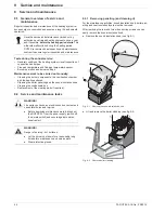
Fig. 7-6

Unscrew the Venturi nozzle with the safety gas control block

Fig. 7-7

Remove the Venturi nozzle with the safety gas control block

Fig. 7-8

Unscrew and remove the venturi nozzle and take off the brass 
bezel

Summary of Contents for A1 BG Inline

Page 1: ...For certified companies ROTEX A1 BG Installation and maintenance instructions Gas condensing boiler For the types A1 BG 25 e A1 BG 25F e A1 BG 40 e A1 BG 40F e GB Output 02 2014 0085 AS 0011...

Page 2: ...ng the operating section RoCon B1 25 6 3 Changing the boiler control panel 25 6 4 Changing cables 26 6 5 Changing the sensors 27 6 5 1 Changing flow return flow temperature sensor 27 6 5 2 Changing th...

Page 3: ...List of contents FA ROTEX A1 BGe 02 2014 3 14 Notes 60 15 For the chimney sweep 64 15 1 Data for designing the flue gas pipe 64 15 2 Emissions measurement 64...

Page 4: ...Heating Systems GmbH declare under our sole responsibility that the products Product Order No Product Order No ROTEX A1 BG 25 e 15 59 35 ROTEX A1 BG 25F e 15 59 36 ROTEX A1 BG 40 e 15 59 42 ROTEX A1 B...

Page 5: ...ROTEX condensing boiler conforms to the state of the art and meets all recognised technical requirements However improper use may result in serious physical injuries or death as well as property damag...

Page 6: ...tion of cor rosion products and deposits Measures for desalination softening or hardness stabilization are necessary if the filling and top up water have a high total hardness 3 mmol l sum of the calc...

Page 7: ...ing return flow cold 10 Heating flow hot 11 Pressure sensor 12 Flue gas supply air connection 13 Condensate box 14 Condensate drain 15 Air supply hose 16 Flame tube 17 Combustion chamber insert 18 Flu...

Page 8: ...ing fault signal provides an engineer with all the necessary information for troubleshooting Electronic control An electronic digital controller combined with the intelligent au tomatic firing unit of...

Page 9: ...experts Fig 4 1 Dimensions of model variants side view legend see tab 4 1 1 Boiler return 1 AG 2 Boiler flow 1 AG 3 Filling line connection on the KFE cock 1 AG 4 Flue gas air intake connection DN 80...

Page 10: ...ler frame and sub tank for legend see tab 4 1 A1 BG 25 F e A1 BG 40 F e Dim on the floor on the sub tank on underframe on the floor on the sub tank on underframe a 400 b 720 c 135 15 785 15 500 15 135...

Page 11: ...b Set up variant for limited room air independent operation flue gas air inlet separate c Set up variant for room air dependent operation d Longitudinally ventilated shaft with fire resistance durati...

Page 12: ...e via the ade quately sealed inlet air through the external wall The air inlet line should be sized so that the suction resistance at nomi nal power is less than 50 Pa Flue gas dissipation to the outd...

Page 13: ...gonal spanner for burner and heat exchanger Recommended accessory Safety group SGB A1 15 60 18 with pressure gauge safety valve automatic bleeding filling cock connection fit tings Connection kit A1 V...

Page 14: ...system must be recognisable on the in stalled system Place the nameplate of the flue system in the installation room Type of connections Straight directly towards rear SET C 15 50 79 03 Height offset...

Page 15: ...4 5 1 The flue system fulfils any other required national or regional safety requirements The ROTEX A1 is installed correctly Connection Connect ROTEX A1 to the flue gas system within the place of ins...

Page 16: ...16 FA ROTEX A1 BGe 02 2014 4 x Set up and installation 4 5 3 Flue gas system kits Fig 4 8 Flue gas system components if necessary...

Page 17: ...of technology to prevent creation of corrosion products and deposits Measures for desalination softening or hardness stabilization are necessary if the filling and top up water have a high total hard...

Page 18: ...ncerning electrical connection All electronic control and safety systems of the ROTEX A1 are connected and tested Modifications on the electrical installation are dangerous and prohibited The operator...

Page 19: ...obe line and connect to the ROTEX A1 controller Connect the external temperature sensors with a dual core cable minimum cross section 1 mm2 Storage tank temperature sensor The storage tank temperature...

Page 20: ...corrugated hose fig 4 10 Item 3 pipe thread EN 2999 Rp to the gas line without tension 4 9 3 Checking burner pre setting Compare the available gas type with the set gas type sticker on burner housing...

Page 21: ...ttings KFE cock fig 4 3 item 3 and secure against sliding by using a hose clamp Open water cock on the supply line Open the KFE cock and observe the pressure gauge in safety group SGB A1 15 60 18 Fill...

Page 22: ...tion ROTEX Controller RoCon BF Check the resistance in the flue gas line see chapter 4 5 1 Check the burner adjustments with a flue gas analyser and readjust if necessary see chapter 7 3 Burner settin...

Page 23: ...on the flow connection and PCB plug inserted Yes 16 Are all sensors connected correctly positioned and activated Yes 17 Mixer group mixer module and mixer circuit sensor optional connected correctly Y...

Page 24: ...und in the documentation of the ROTEX RoCon BF Reglator 1 Mains switch 2 Operating part RoCon B1 3 Clear text display 4 Rotary switch 5 Setting Info 6 Setting Operating Mode 7 Setting Set Temp Day 8 S...

Page 25: ...1 3 Remove both top heat insulation shells see chapter 9 2 1 4 Unscrew the switching panel cover and remove fig 6 3 5 Pull out all plugs from the switchboard PCB fig 6 4 6 Pull out the sensor and the...

Page 26: ...in the unit are con nected to the circuit board connectors and cannot be released They can be released from the respective compo nents where they are plugged in The cables for external components e g...

Page 27: ...d Do not force the connector WARNING Live parts can cause an electric shock on contact and cause life threatening burns and injuries Before beginning work on the ROTEX A1 disconnect therom the power s...

Page 28: ...re sensor is connected directly to the connection terminals 9 and 10 of the 12 pin sensor connector J8 in the boiler control panel 1 Open the boiler control panel and pull connector J8 off the circuit...

Page 29: ...t in the electrical system Have a professional electrician remedy the cause of the short circuit before putting in a new fuse 1 Mains switch 2 Operating part RoCon B1 16 Switchboard PCB 17 Communicati...

Page 30: ...30 FA ROTEX A1 BGe 02 2014 6 x Control unit Fig 6 16 Wiring diagram ROTEX A1 BG for legend see tab 6 1...

Page 31: ...ment connection IN input gas pressure 10 Measurement connection OUT output gas pressure 11 Gas air mixture set screw 12 Gas pressure controller set screw beneath cover cap 13 Burner flange 14 1 Ionisa...

Page 32: ...s automatic firing CM124 R1 controlled by a micropro cessor controls and monitors the firing programme and the temperature sensors for the flow and return temperature It features the following propert...

Page 33: ...ation is installed The blower type can be read off of the type plate of the blower near the outlet flange on the blower housing If changes have been made to the power settings of the burner or if it h...

Page 34: ...burner ROTEX Factory settings Tab 7 2 Flue gas set values and speed limits for A1 BG 25 F e for different types of gas A1 BG Type A1 BG 40 F e G1G 126 Blower type Gas type Test gas Setting for control...

Page 35: ...th the specified setting values see section 7 3 1 11 If the CO2 concentration is outside 0 2 or the O2 concentration is outside 0 3 of the set target values Readjust burner using the adjusting screw f...

Page 36: ...uri nozzle fig 7 8 step 2 7 Remove the brass bezel between the safety gas control block and the venturi nozzle fig 7 8 step 3 8 Using the 3 screws screw the Venturi nozzle back on the safety gas contr...
Page 37: ...out by Determining the matching setting values for the desired out put from fig 12 4 to fig 12 7 or tab 7 2 and tab 7 3 Limiting the maximum burner output The limiting of the maximum burner output wou...

Page 38: ...start power may help For deflagrations Reduce the starting output For starting problems such as burner whistling or flame forming Increase the starting output To change the starting output 1 Enter the...

Page 39: ...ctrodes are factory set to the optimum value For adjusting see fig 7 10 CAUTION Ignition electrodes can break with cold deformation Dismantle the burner before adjusting the electrodes and make the el...

Page 40: ...e all electrical plug connections 3 Connect the air supply hose to the burner 4 Open gas intake and check gas line for leaks 5 Turn power supply back on 6 Start the burner Check function and setting s...

Page 41: ...tem must be connected to the return line There should be no hydraulic blocking ele ments between the heat generator and the safety valve Locate the diaphragm expansion vessel in an easily accessible p...

Page 42: ...to centre position with hand lever fig 8 4 item 3 3 only possible if the valve drive is already in Heating position 1 T Piece 3x1 2 Ball cock 1 2x 3 3 way diverter valve 3UV1 3 1 Valve drive 3 2 Unlo...

Page 43: ...n return valves 3UV1 3 way switch valve DHW A1 A1 oil or gas condensing boiler CW Cold water DHW Domestic hot water S O Hot water storage tank SC 538 16 0 H1 H2 Hm Heating circuits MAG Diaphragm expan...

Page 44: ...ation hood boiler pan elling and heat insulation layers must be removed After removing the rear and two side securing screws you can easily remove the sound insulation hood Remove the sound insulation...

Page 45: ...ch it drain The water must flow quickly without puddling If the water doesn t drain quickly the condensate box must be cleaned and the drain connector checked see Dismount ing and cleaning the condens...

Page 46: ...xible connector hose and drain connector and clean if necessary 8 Push condensate box under the boiler 9 Plug flexible connector hose onto the condensate box see fig 4 11 10 Place the connection sleev...

Page 47: ...ner see chapter 7 3 Opening the combustion chamber Special tool Combustion chamber key fixed on the inside of the boiler panels included in the supply Remove four M10 inner hex screws fig 9 11 Hinge t...

Page 48: ...and cleaning scraper Rinse off loosened dirt with clean water into the drain Alternatively any residue can be removed with a high pressure cleaner For this Close combustion chamber without combustion...

Page 49: ...ment operating mode Check combustion values Flue gas temperature at measuring sockets of the flue gas pipe Target value 90 C O2 or CO2 content see chapter 7 3 1 Settings CO content target value 50 ppm...

Page 50: ...not functioning main switch not illuminated no display No mains voltage Switch on the main switch for the boiler Turn on main switch of heating room Check switch on fuse house connection Check renew f...

Page 51: ...st or replace if necessary Distance of ignition electrodes too large Check ignition electrodes and adjust if necessary Ignition electrodes contaminated or humid Clean ignition electrodes and check bur...

Page 52: ...E34 BCC data conflict E35 Necessary BCC not detected E36 BCC data conflict E37 BCC firmware does not match automatic firing firmware E38 Wrong BCC number E39 BCC system fault E99 Safety shutdown E6 A...

Page 53: ...not actuate The ROTEX A1 operates manually at the set flow temper ature 4 Cancelling and jump back by pushing the Exit button again Code Component Designation Fault Possible fault rectification E75 O...

Page 54: ...stem at the filling and draining sockets KFE cock 11 2 Final shutdown and disposal For the final shutdown the ROTEX A1 must be Taken out of service Disconnect it from all electrical gas and water conn...

Page 55: ...permitted operating temperature 90 C Maximum permitted operating overpressure PMS 4 bar Maximum boiler efficiency 109 Energy efficiency according to efficiency guidelines Flue gas temperature 85 C Flu...

Page 56: ...g circulation pump and the 3 way diverter valve from connecting kit VSA1 Gas type Rated pressure in mbar Min inlet pressure in mbar Max inlet pressure in mbar Natural gas E H 20 17 25 Natural gas LL L...

Page 57: ...ner load of the ROTEX A1 BG 25 F e Fig 12 3 Permissible burner load of the ROTEX A1 BG 40 F e legend see fig 12 2 pR Remaining pumping height mH Flow heating network Fig 12 4 Residual conveying height...

Page 58: ...ccording to standard or manufacturer s indications NTC tV tR tAU tDHW tMi 98660 56250 33210 20240 12710 8195 5416 3663 2530 1782 1278 932 690 519 395 PT 1000 tAG 922 961 1000 1039 1077 1116 1155 1194...

Page 59: ...lue gas mass flow 15 Flue gas temperature probe 28 Check 47 Flue system Dimensioning 14 Kits 16 Minimum requirements 14 Piping height 14 Flue system kits 16 Fuel 6 Fuse 29 G Gas connection Execution 2...

Page 60: ...60 FA ROTEX A1 BGe 02 2014 14 x Notes 14 Notes...

Page 61: ...14 x Notes FA ROTEX A1 BGe 02 2014 61...

Page 62: ...62 FA ROTEX A1 BGe 02 2014 14 x Notes...

Page 63: ...14 x Notes FA ROTEX A1 BGe 02 2014 63...

Page 64: ...oad type Full Load using the rotary switch but do not confirm it Display Full Load The burner is turned on for 30 min and is regulated at maximum load Select the load type Base Load using the rotary s...

Reviews: