9
x
Service and maintenance
FA ROTEX A1 BGe - 02/2014
47
9.2.4 Checking the flue gas temperature
The flue gas temperature can be checked
– on the operating panel in the boiler control panel, rotary
switch in position:
"Info"
,
– on the measuring piece of the flue gas pipe by using a flue
gas thermometer.
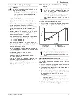
If the flue gas temperature exceeds the boiler temperature by
over 20 K after 10 mins. of burner operation, the combustion
chamber will have to be cleaned (see section 9.2.5).
Checking the flue gas temperature sensor
Ɣ
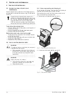
Unscrew the box nut (fig. 9-10, item 4) and pull out the flue
gas temperature sensor carefully with the guide sleeve
(fig. 9-10, item 3).
Ɣ
Check the flue gas temperature sensor for cleanliness and
corrosion and clean if necessary. Do not use any metallic
cleaning devices (e.g. wire brush).
Ɣ
When replacing the flue gas temperature sensor, ensure that
the end of the flue gas temperature sensor projects
28
±
2 mm
out of the guide sleeve.
9.2.5 Checking and cleaning the combustion
chamber
If there are impurities, or if unsatisfactory combustion values are
detected, the combustion chamber must be cleaned and
readjusted. If necessary, reset the burner (see chapter 7.3)
Opening the combustion chamber
Special tool:
Combustion chamber key, fixed on the inside of the
boiler panels (included in the supply).
Ɣ
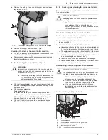
Remove four M10 inner hex screws (fig. 9-11).
Ɣ
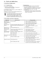
Hinge the top half of the burner chamber upwards (fig. 9-12).
An air pressure spring keeps the upper half of the combustion
chamber open.
CAUTION!
The fitting position of the flue gas temperature sensors
is factory-adjusted by a fixing screw. Modifying the
fitting position adversely affects the correct functioning
of the flue gas temperature sensor.
Ɣ
Never loosen the fixing screw (fig. 9-10, item 2)
when inspecting the flue gas temperature sensor.
1
Sensor cable to the boiler control panel
2
Fixing screw - Do not loosen!
3
Guide bush
4
Union nut
5
Flue gas temperature sensor
Fig. 9-10 Position of the flue gas temperature sensor
WARNING!
Live parts can cause an electric shock on contact and
cause fatal burns and injuries.
Ɣ
Before beginning maintenance work, disconnect
the ROTEX A1 from the power supply (switch off
fuse, main switch) and secure against uninten-
tional restart.
WARNING!
Danger of burning - hot surfaces.
Ɣ
Before starting work on the burners, the
combustion chamber and the combustion chamber
inserts, allow them to cool down.
Ɣ
Wear protective gloves.
Fig. 9-11 Opening the combustion chamber
Fig. 9-12 Hinge the top half of the burner chamber upwards.


