


BRP-Rotax
INSTALLATION MANUAL
Illustrations
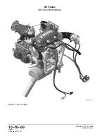
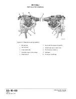
The illustrations in this Manual are merely sketches and show typical arrangements. They
may not represent full detail or the exact shape of the parts but should outline the same or
similar function. Therefore deriving dimensions or other details from illustrations is not
permitted.
TYPICAL indicates a general view which may not represent exact details.
N
NO
OT
TE
E
The Illustrations in this Manual are stored in a graphic data base system and are
provided with a consecutive irrelevant number.
This number (e.g. AE 5iS001) is of no significance for the content.
Some measurements are given in the drawings, these are manufacturing dimensions and
are subject to corresponding tolerances.
Installation
drawings
Installation drawings and a DMU-model for (virtual) installation analysis are available from
the ROTAX® Authorized Distributors or their independent Service Centers on special re-
quest and relevant non disclosure and copyright regulations.
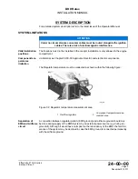
The illustrations in this Manual shows a possible installation variant included non certified
parts.
Effectivity: 915 i A Series
Edition 0/Rev. 0
Page 15
December 01 2017
Summary of Contents for 915 iS 3 A
Page 165: ......