


BRP-Rotax
INSTALLATION MANUAL
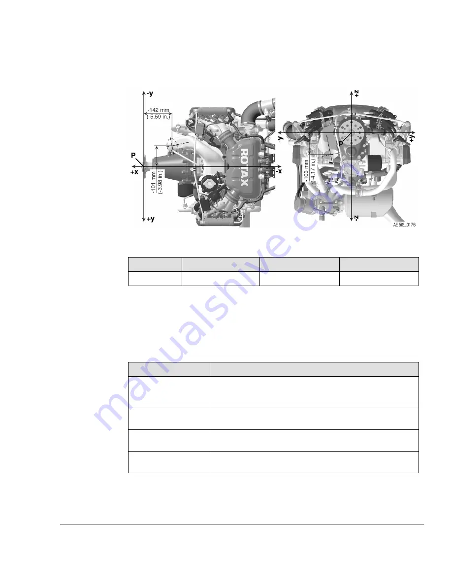
AIR COOLING INTERFACES
Cooling air baffle
Figure 8.5: Cooling air baffle position
Position
x-axis
y-axis
z-axis
P1
- 142 mm (- 5.59 in.)
- 101 mm (- 3.98 in.)
- 106 mm (- 4.17 in.)
Cooling air baffle
N
NO
OT
TE
E
In some special cases a separate cold air supply to the air filter should be
provided.
Following recommendations should assist the aircraft or fuselage manufacturer in select-
ing suitable cooling air ducts:
Specification
Description
Cooling capacity
The cooling air baffle must be designed so, that it transfers
thermal energy of approx. 6 kW (5.7 BTU/s) at take-off
performance.
Cross section of air
baffle
Cross section of the air baffle min. 100 cm² (15.50 in
2
).
Material
Glass fibre reinforced plastic or heat and fire resistant
material.
Attachment options
Formlocking on engine block and mounting above the cylinder
and the crankcase.
Effectivity: 915 i A Series
Edition 0/Rev. 0
Page 7
December 01 2017
Summary of Contents for 915 iS 3 A
Page 165: ......