


BRP-Rotax
INSTALLATION MANUAL
INTERFACE DESCRIPTION
INTERFACE OVERVIEW
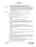
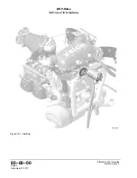
Figure 13.2: Starter interfaces
1
Positive terminal
2
Negative terminal
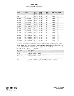
ELECTRICAL INTERFACES
Positive terminal
Interface Parameter
Min.
Max.
Nominal
Input voltage:
12 V
Input load:*
* for resistance of starter circuit
Rsmax = <20 mOhm
20 A
350 A
3
The terminal must be conducted as M5 screw connection suitable for cable lug according
to DIN 46225.
Tightening torque: Min. 3 Nm (27 in.lb) Max. 5 Nm (44 in.lb).
Negative terminal
The engine block must be connected to the airframe using a properly sized ground strap
(minimum the same cable cross section as the starter supply), for carrying the starter cur-
rent and to avoid static electricity between the engine and the airframe.
Page 4
December 01 2017
Effectivity: 915 i A Series
Edition 0/Rev. 0
3.
When starter engine is locked
Summary of Contents for 915 iS 3 A
Page 165: ......