60
14.3 Adjustment work
1. To begin making adjustments, first roughly level
the runways.
2. To do so, adjust the 4 cables in such a way that
the loaded runways of the lift are horizontal both
lengthwise and diagonally.
To do this, place a spirit level onto the surface
of the runway first lengthwise and then onto the
cross beam.
Turn table
55
3. Lock the lift into the latch bar.
4. Adjust the cables with the nuts on the cable end.
Then lock the nuts. Make sure that all latches are
at the same height.
Adjust the runways according to the requirements
of the vehicle manufacturer. To do so, the
following measuring equipment is required:
•
Automatic level
•
Measuring stand with scale in mm.
5. Drive the vehicle onto the lift so that the front
wheels stand on the turning radius gauge and the
rear wheels on the slip plate.
The vehicle must come to a halt virtually centered
on the lift in the direction of motion.
6. Loosen the lock pins on the turning radius gauge
and slip plates. Make sure that the vehicle can
now slip easily on the plates and that no tension
exists so that the adjustment work can be carried
out precisely.
7. Now lower the lift into the bottom position.
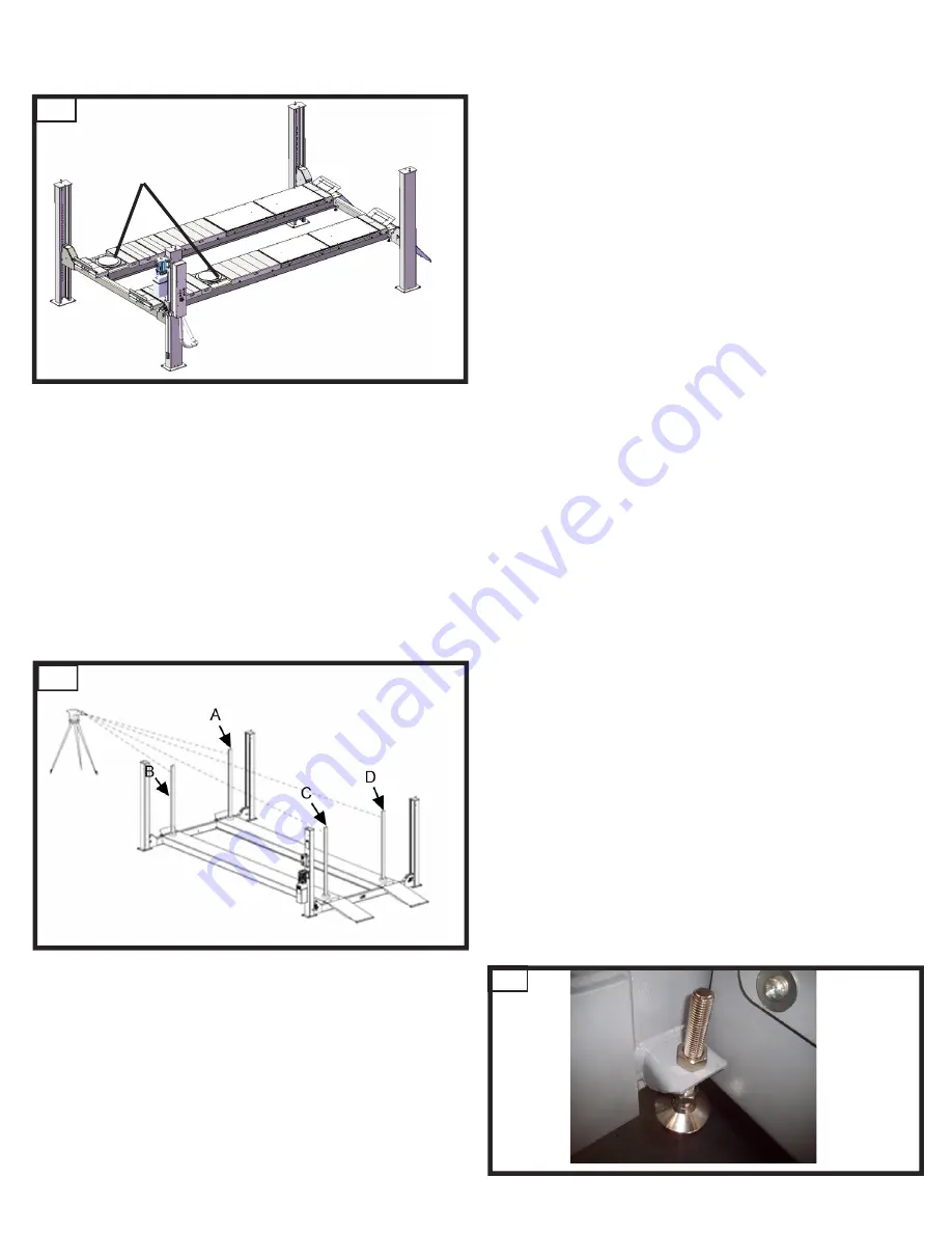
8. Position the automatic level so that the
measuring stands can be seen positioned one
behind the other on the wheel footprints.
9. For each wheel footprint, note the measurements
according to the scale on the measuring stand.
10. Using the 4 cross beam adjustment screws
in the "bottom position“, (
→
Fig. 46) adjust the
height so that the readings from all 4 measuring
points are the same after they have been
checked again.
57
56


