background image

The Crop Mark Feature

3.

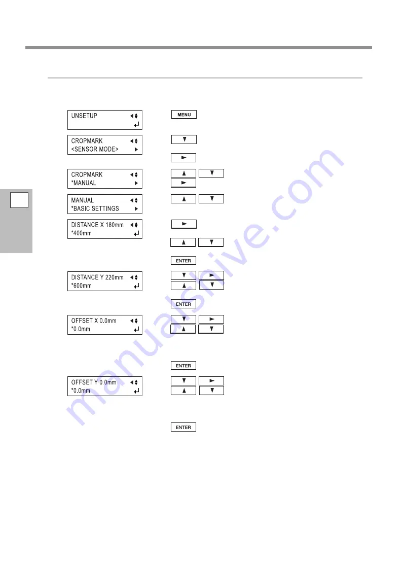
Select the operation mode and enter the setting values.

Set the [CROPMARK] menu item to [MANUAL], then manually enter the values such as the distances between 
the crop marks you drew when you created the figure.

Press

several times until the screen shown in the 

figure appears.

Press

several times until the screen shown in the 

figure appears.

Press

.

Press

to select [MANUAL].

Press

.

Press

to select [BASIC SETTINGS].

Press

several times until the screen shown in the 

figure appears.

Press

to enter the horizontal distance between 

the crop marks.

Press

to enable the setting.

Press

to show the screen in the figure.

Press

to  enter  the  vertical  (lengthwise)  dis

-

tance between the crop marks.

Press

to enable the setting.

Press

to show the screen in the figure.

Press

to enter the horizontal distance between 

the origin point for the cutting location and the origin point 

for printing. 

This is normally set at 0 mm.

Press

to enable the setting.

Press

to show the screen in the figure.

Press

to  enter  the  vertical  (lengthwise)  dis

-

tance between the origin point for the cutting location and the 

origin point for printing.

This is normally set at 0 mm.

Press

to enable the setting.

3

Part of 

Practice

66

Summary of Contents for Camm-1Pro GX-300

Page 1: ...cifications of this product are subject to change without notice The operation manual and the product have been prepared and tested as much as possible If you find any misprint or error please inform us Roland DG Corp assumes no responsibility for any direct or indirect loss or damage which may occur through use of this product regardless of any failure to perform on the part of this product Rolan...

Page 2: ...a risk of electric shock The conductor with insulation having an outer surface that is green with orwithoutyellowstripesistheequipment grounding con ductor If repair or replacement of the electric cord or plug is necessary do not connect the equipment grounding conductor to a live terminal Checkwithaqualifiedelectricianorservicepersonnelifthe groundinginstructionsarenotcompletelyunderstood orif in...

Page 3: ...Test Feed 40 Downloading Cutting Data 41 To Sever the Material 41 Pausing and Resuming Cutting 41 To Change the Cutting Speed or Blade Force During Cutting 42 When Cutting is Completed 42 Chapter 3 Part of Practice 45 Detailed Cutting condition Settings 46 Adjusting the Blade Extension 46 Adjusting the Blade Offset 47 Changing the Speed When Raised Up Speed 47 Settings for Cutting Quality 48 Detai...

Page 4: ...erial Easy to be Winkled Hard to be Fed 71 Important Note and Advice in Using Special Material 72 Chapter 4 Maintenance FAQ 73 Maintenance 74 Cleaning 74 Consumable Items 75 How to Replace the Separating Knife 76 Self test Operation Check 77 What to Do If 78 The Machine Doesn t Run 78 Cut Lines Are Uneven or Not Cut Attractively 79 Uncut Areas Remain or the Material Is Not Cut 79 The Carrier Paper...

Page 5: ...ace Specifications 94 Serial 94 USB 94 Serial connector 94 USB connector 95 XY RS 34 serial cable connection 95 Specifications 96 Company names and product names are trademarks or registered trademarks of their respective holders Copyright 2010 Roland DG Corporation http www rolanddg co jp This document is the setup guide for four models GX 640 500 400 300 Also most of the figures in this document...

Page 6: ...espect to the home and all its furnishings as well to domestic animals or pets About the Symbols The symbol alerts the user to important instructions or warnings The specific meaning of the symbol is determined by the design contained within the triangle The symbol at left means danger of electrocution The symbol alerts the user to items that must never be carried out are forbidden The specific th...

Page 7: ...r attachment or detachment of optional items disconnect the power cord Attempting such operations while the ma chine is connected to a power source may result in injury or electrical shock WARNING Never attempt to disassemble repair or modify the machine Doing so may result in fire electrical shock or injury Entrust repairs to a trained service technician CAUTION Exercise caution to avoid being pi...

Page 8: ...hort shock electrocution or fire WARNING Handle the power cord plug and electri cal outlet correctly and with care Never use any article that is damaged Using a damaged article may result in fire or electrical shock When using an extension cord or power strip use one that adequately satisfies the machine s ratings for voltage fre quency and current Use of multiple electrical loads on a single elec...

Page 9: ...the power cord plug and electrical outlet Never place any object on top or subject to damage Never bend or twist with undue force Never pull with undue force Never bundle bind or roll up Never allow to get wet Never make hot Dust may cause fire ...

Page 10: ...ormed by 4 per sons or more Tasks that require undue effort when per formed by a small number of persons may result in physical injury Also if dropped such items may cause injury Be sure to lock the stand s casters If the machine should begin to topple a ma jor accident may result including crushing of the appendages or the body WARNING When storing roll media implement adequate safety measures to...

Page 11: ...ed their warnings Also never remove the labels or allow them to become obscured Warning Labels Caution Moving Carriage The cutting carriage moves at high speed and pose a hazard Keep your hands away from it Caution Entanglement Hazard Never inadvertently allow hands hair clothing such as neckties or the like near rotating parts while in operation ...

Page 12: ...re effet indésirable sur la maison tous les meubles et même les animaux domestiques À propos des symboles Le symbole attire l attention de l utilisateur sur les instructions importantes ou les avertissements Le sens précis du symbole est déterminé par le dessin à l intérieur du triangle Le symbole à gauche signifie danger d électrocution Le symbole avertit l utilisateur de ce qu il ne doit pas fai...

Page 13: ...ation et autres articles semblables compatibles avec l appareil Les articles incompatibles risquent de causer des accidents PRUDENCE Faire preuve de prudence pour éviter l écrasement ou le coincement La main ou les doigts peuvent être écrasés ou coincés s ils entrent en contact avec certaines surfaces par inadvertance Faire preuve de prudence pendant l utilisation de l appareil Ne jamais faire fon...

Page 14: ...ustion ou une explosion pour raient se produire Risque de décharge ou de choc électrique d électrocution ou d incendie ATTENTION Manipuler le câble d alimentation la fiche et la prise électrique correctement et avec soin Ne jamais utiliser un article endommagé car cela pourrait causer un incendie ou un choc électrique Si une rallonge ou une bande d alimentation électrique sont utilisées s assurer ...

Page 15: ...sur la fiche ou sur la prise car cela risque de les endommager Ne jamais plier ni tordre le câble avec une force excessive Ne jamais tirer sur le câble ou la fiche avec une force excessive Ne jamais plier ni enrouler le câble Ne jamais laisser l eau toucher le câble la fiche ou la prise Ne jamais chauffer le câble la fiche ou la prise La poussière peut causer un incendie ...

Page 16: ...es qui exigent un effort trop grand si elles sont exécutées par un petit nombre de personnes peuvent être cause de bles sures La chute d articles très lourds peut aussi causer des blessures ATTENTION S assurer de verrouiller les roulettes de la base Si l appareil devait commencer à basculer il s ensuivrait un accident grave par exemple l écrasement de membres ou du corps Prendre les mesures de séc...

Page 17: ...isse ments Ne jamais retirer les vignettes et ne pas les laisser s encrasser Vignettes d avertissement Attention Chariot mobile Le chariot de coupe se déplace très rapidement et peut être dangereux Tenir les mains loin du chariot Attention Danger d emmêlement Toujours éloigner les mains les cheveux les vêtements ou des accessoires comme des cravates des pièces tournantes pen dant que l appareil fo...

Page 18: ...lso cause malfunction or breakdown Main Unit This Machine Is a Precision Device Handle carefully and never subject the machine to impact or excessive force Install in a Suitable Location Install in a location having the specified temperature and relative humidity Install in a quiet stable location offering good operating conditions Important Notes on Connecting the Cables Connect the power cord an...

Page 19: ...1 Getting Started Chapter 1 Getting Started Part Names and Functions 18 Front 18 Rear 19 Operation Panel 20 Menu List 21 Menu List 21 17 ...

Page 20: ...t this at the right hand edge of the material Operation panel P 20 Operation Panel Platen Blade protector Sheet sensor Tool carriage The tool carriage is where a blade or the alignment tool is mounted Separating knife This cuts off a piece of ma terial from roll material Power switch ON when switched to OFF when switched to O Guide lines These are used as guides formakingsuretheloaded material is ...

Page 21: ...lower the pinch rollers Tray Use this to store blades Sheet sensor Brake Power connector Connect the power cord in cluded with the machine to this connector USB connector This is for connect ing a computer with a USB cable Serial connector Thisisforconnectinga computer with a serial cable ...

Page 22: ...witches se quentially among the present cutting condition the menu mode and the width display screen P 87 List of Functions SPEED Key This key sets the cutting speed P 39 Adjusting the Cutting Speed POWER LED This lights up when the power is switched on ORIGIN Key This key sets the origin point P 40 Setting the Origin Point FORCE Key This key sets the blade force P 38 Adjusting the Blade Force PAU...

Page 23: ...1 Getting Started 21 Menu List Menu List ...

Page 24: ...1 Getting Started Menu List 22 ...

Page 25: ...1 Getting Started Menu List 23 ...

Page 26: ...24 ...

Page 27: ...e Adjustment of a Blade 35 Installing a Blade 35 Cutting Test 36 Adjusting the Blade Force 38 Adjusting the Cutting Speed 39 Starting Quitting Cutting 40 Setting the Origin Point 40 Material Test Feed 40 Downloading Cutting Data 41 To Sever the Material 41 Pausing and Resuming Cutting 41 To Change the Cutting Speed or Blade Force During Cutting 42 When Cutting is Completed 42 25 ...

Page 28: ...ons of the grit rollers pinch rollers that secure the material vary from one model to another The settable ranges for the left and right movable pinch rollers are predetermined and cannot be changed Refer to the page 29 30 31 and 32 Material Loading Position Setting a pinch roller outside the allowed range causes an error message to appear Loading Roll Material When performing lengthy cutting of 1...

Page 29: ...ers to raise the pinch rollers Place the roll material on the shafts Release the brake Pass the end of the material between the pinch rollers and the grit rollers so that it extends from the front of the unit Sheet loading levers Sheet loading levers Sheet hanger Shafts Stoppers Brake ...

Page 30: ...aneously lies over any of the other grit rollers Performing high speed cutting when only a little roll material remains may cause the roll to fall off the shafts If this happens it may help to pass the shaft through the roll Grit marks These indicate the position of the grit rollers Grit rollers Material Sensor Load the material so that it lies over the sensor on the platen Grit roller right ...

Page 31: ...ight hand movable pinch roller Material with a width of 64 in Material with a width of 60 in Material with a width of 54 in Materialwitha width of 48 in Materialwitha width of 36 in Materialwitha width of 30 in Materialwitha width of 24 in Material with a width of 18 in Materialwitha width of 12 in Materialwitha width of 6 in 1 2 3 4 Make sure the pinch rollers are positioned above the grit patter...

Page 32: ...and movable pinch roller Material with a width of 48 in and 54 in Material with a width of 36 in Material with a width of 30 in Material with a width of 24 in Materialwitha width of 18 in Material with a width of 12 in Material with a width of 6 in 1 2 Make sure the pinch rollers are positioned above the grit pattern 1 Position of the pinch roller middle when using material with a width of 30 in o...

Page 33: ...width other than one indicated above move the right hand movable pinch roller Materialwitha width of 36 in and 46 in Materialwitha width of 30 in Material with a width of 24 in Materialwitha width of 18 in Material with a width of 12 in Material with a width of 6 in 1 Make sure the pinch rollers are positioned above the grit pattern 1 Position of the pinch roller middle when using material with a ...

Page 34: ... Position Material 6 in approx 152 mm 12 in approx 305 mm 18 in approx 457 mm 24 in approx 610 mm 30 in approx 762 mm The right hand movable pinch roller can be moved within this range When loading material with a width other than one indicated above move the right hand movable pinch roller Acceptable material widths 50 to 540 mm 2 in to 21 in 582 to 915 mm 23 in to 36 in Material with a width of ...

Page 35: ...responding grit roller If the pinch rollers do not move smoothly try moving them by grasping near the base of the sheet loading lever at the back of the unit Raise the sheet loading levers The pinch rollers are lowered and the material is secured in place When using a material which is narrower than 762 mm 30 in do not lower the middle pinch roller Position the stoppers so that they lightly touch ...

Page 36: ...nload the material refer to the page 42 When Cutting is Completed or press to clear the error then reposition the pinch rollers correctly to load the material precisely When using roll material before you perform cutting you need to pull out the required length of material from the roll For more information refer to the page 40 Material Test Feed Be sure to use the middle pinch roller for the wide...

Page 37: ...t supporting the screw in this way the blade tip may strike the blade protector damaging the blade or blade protector and impairing cutting quality Procedure Insert the pin into the blade holder Insert the blade Tighten the cap all the way Support the screw from below and insert the blade holder If installed without supporting the screw in this way the blade tip may strike the blade protector dama...

Page 38: ...he place where the cutting test is to be performed An area of approximately 2 square centimeters a little less than a square inch is required to make a test cutout given that the tip of the blade after it has moved is at the origin at lower left Hold down for 0 5 seconds or lon ger Cutting test starts When you re using general sign material use with the cap tightened all the way to the top maximum...

Page 39: ... For more information refer to the page 57 Front Loading For Materials with a Strong Adhesive Layer If you are using a material with a strong adhesive layer the adhesive layer may adhere to itself im mediately when cut This means that even though the material has actually been cut it may appear as if it has not been cut and blade force may mistakenly be set too high If a cutting test shows that th...

Page 40: ...o set the blade force if you want to raise or lower the blade force slightly you can use the PEN FORCE slider to make fine adjustment Move the slider to the right or left to gradually raise or lower the blade force and set it at an appropriate value The range of the fine adjustment using the PEN FORCE slider is within 30 gf up or down from the value set with the operation panel When using the oper...

Page 41: ...lade force The material peels during the cutting The blade requires frequency replacement Cutting extends through the base paper and normal advancing of the material becomes impossible The blade protector is damaged Some parts of the material remain uncut Cutting speed Uncut areas remain in places The cut depth differs according to the location nonuniform cut ting depth The material peels The cut ...

Page 42: ...during cutting a motor error may occur or the position may be displaced Test feed can also be performed to make sure that the loaded material is straight Using the AREA feature makes it simple to perform test feed for the required portion Make sure that the type of the material has been selected using the operation panel and that material loading has been completed Procedure Make sure the brake is...

Page 43: ...y press or turn off the power switch on the right side of the machine To Sever the Material With this machine it is possible to cut off the material after performing cutting Holding down for 0 5 seconds or longer severs the material Pausing and Resuming Cutting To suspend or resume the process during cutting perform the following operation Procedure Press Cutting is paused and the screen shown in ...

Page 44: ...or longer You can also perform fine adjustment in blade force while cutting is in progress by using the PEN FORCE slider P 38 Adjusting the Blade Force p 39 Adjusting the Cutting Speed When Cutting is Completed CAUTION When not in use for extended periods unplug the power cord from the electrical outlet Failure to do so may result in danger of shock electrocution or fire due to deterioration of th...

Page 45: ...securing screw and remove the blade holder from the tool carriage Press the pin and remove the blade from the blade holder As debris of material or paste might cling to the tip of a used blade wipe it with a soft cloth to remove them Press the pin Blade holder Blade Remove the material POWER LED goes out Tool carriage Tool securing screw ...

Page 46: ...44 ...

Page 47: ...ront Loading 57 Loading Material 57 Setting the Cutting Area Using the Operation Panel 58 Setting the Cutting Area Using the CAMM 1 Driver 59 The Overcut Feature 61 About the Overcut Feature 61 Setting Overcutting to ENABLE 61 The Memory Feature 62 About the Memory Feature 62 To Store in Memory 62 Calling Up 63 Deleting Settings 63 The Crop Mark Feature 64 About the Crop Mark Feature 64 Using the ...

Page 48: ... full turn Adjusting the cutting in amount Turn the cap portion to adjust the amount of blade extension which is approximately equal to the cutting in amount Setting the blade force slightly higher than normal achieves a stable cutting in amount Rough Estimate for the Amount of Blade Extension Use the following dimension as a rough estimate for setting the amount of blade extension Min 0 mm Cap Ma...

Page 49: ...ress several times until the screen shown in the figure appears Press Press to set the value Press to enable the setting Press to go back to the screen shown in the figure Changing the Speed When Raised Up Speed With this machine you can set the speed for movement to the next cutting location with the tool raised while cutting is in progress In cases such as when the material rises up over the pla...

Page 50: ... Press several times until the screen shown in the figure appears Press Press Press several times until the screen shown in the figure appears Press Press to set the value Press to enable the setting Press to go back to the screen shown in the figure Setting range AUTO 10 to 50 cm s in increments of 10 cm s Adjusting Cutting Quality Setting range NORMAL HEAVY HI SPEED When you want cutting to be a...

Page 51: ...ration panel when loading material Setting when material is loaded Location of the origin point ROLL Set near the left hand pinch roller F EDGE Set at the front left edge of the material R EDGE Set at the inner left edge of the material When using the Front loading PIECE Material size is detected and the origin is set at the lower left area of the material For more information see the following pa...

Page 52: ...ocationhavingamarginof30 mm 1 3 16 in from the trailing edge of the material When in this state the cutting area is zero PIECE When using flat material After length in the direction of material feed is de tected movement 30 mm 1 3 16 in back from the frontedgeofthematerialisperformed andtheorigin point is set near the left pinch roller When the length of the material is 1 600 mm 63 in or longer th...

Page 53: ... 90 degrees the X axis Y axis and origin point change as follows Note that the coordinate axes change when rotated Make the settings to match the program you re using When this is set to 90deg on the operation panel then the CAMM 1 driver s Rotate setting must be set to Rotate off Procedure Press several times until the screen shown in the figure appears Press Press Press several times until the s...

Page 54: ...e of material that is about 100 mm 3 15 16 in longer than the vertical size of the cutting data is required When you select F EDGE or PIECE this is 30 mm 1 3 16 in When you select ROLL everything toward the front from the origin point is the margin P 49 The Location of the Origin Point Immediately After Loading Material When you have separated the material using this is the value set for MARGIN at...

Page 55: ...al By doing so the material can be installed without crook and it will prevent the material from coming off When performing the lengthy cutting we highly recommend that you turn OFF the AUTO FEED as the feature is unsuitable to the lengthy cutting The AUTO FEED feature is available only for GX 640 P 91 Description of Menu Items OTHERS AUTO PREFEED Lengthy Cutting Loading Material NOTICE When perfo...

Page 56: ...ht pinch rollers position the middle pinch roller above the correspond ing grit roller While keeping the material stretched taut raise the sheet loading levers to secure the material in place Position the stoppers so that they lightly touch the edges of the roll and secure in place by tightening the screws Release the brake Pinch roller Left Pinch roller middle 25 mm 1 in or more Guide line Brake ...

Page 57: ...he screen shown in the figure appears Press Perform the test feed of the material by following the proce dures of and after on P 40 Material Test Feed If the material is crooked and looks like it might come loose from the pinch rollers press and hold down for 0 5 seconds or longer to stop material Then load the material again ...

Page 58: ... ahead to procedure Press Press to select CLEAR Press to enable the setting The data in the replot memory is deleted Press to go back to the screen shown in the figure 2 Start replotting Press several times until the screen shown in the figure appears Press several times until the screen shown in the figure appears Press Press Replotting starts About the replot feature The Replot feature performs ...

Page 59: ...erial Procedure Refer to the page 26 Loading the Material Roll Material and load the material When the left figure is displayed press to select either ROLL or R EDGE Press to enable the setting Do not select F EDGE Set a origin point Follow the steps in About the Origin Point and the Cuttable Area in the next section to set a new origin point In particular not that if you have selected R EDGE cutt...

Page 60: ... is set to 0 deg The material is always fed toward the front of the machine as cutting proceeds This is why the area where cutting is possible is to the rear of the origin point This means that even when the setting is R EDGE or ROLL it is necessary to feed the material toward the rear and then set a new origin point to make the required cutting area available With front loading you can use either...

Page 61: ...ding the required cutting area is set by the computer Procedure Refer to the page 26 Loading the Material Roll Material and load the material When the left figure is displayed press to select either ROLL or R EDGE Press to enable the setting At the CAMM 1 driver s Properties window click the Options tab then select Front Loading On the Size tab make the setting for Cutting Area The cutting area of...

Page 62: ...igin for automatically making the cut ting area available using Front Loading It makes no difference where the origin point has been set Present position of the tool is used as the point for origin in not only feed direction but also right and left direction Cutting area Tool location at cutting start ...

Page 63: ...ate shapes cutting in may occur on the portion of the material you are using and so this should be set at DISABLE Cutting results differ as shown in the following figures depending on whether the Overcut function is disable or enable Setting Overcutting to ENABLE Procedure Press several times until the screen shown in the figure appears Press several times until the screen shown in the figure appe...

Page 64: ... mode OFFSET Cutting speed Cutting quality Menu mode QUALITY Up speed Menu mode UP SPEED Press several times until the screen shown in the figure appears Press Press Press Press Press to select the user number for the condi tions you want to store in memory Press to enable the setting Press to go back to the screen shown in the figure When you store to a user number any cutting conditions already ...

Page 65: ...em to their factory defaults Please note that all user numbers from 1 to 8 are deleted This resets to their default values not only the memory settings but also all menu settings Procedure Press several times until the screen shown in the figure appears Press several times until the screen shown in the figure appears Press Press several times until the screen shown in the figure appears Press Pres...

Page 66: ...ible to adjust the location to cut When you use this feature the operation method differs according to the program you re using Using the Included Program Using the included Roland CutStudio program enables you to print together with the image crop marks that the machine s sensors can automatically detect then perform alignment automatically and carry out cutting For information on how to perform ...

Page 67: ...uring left and right margins of about 25 mm 1 in each Be sure to make a note of the distances between the crop marks distance X and distance Y in the figure below These need to be entered into the machine later There are no rules specifying the shape of the crop marks but using square angle shapes like those shown in the figure can facilitate alignment 2 Get ready to perform cutting When you have ...

Page 68: ...ss to enter the horizontal distance between the crop marks Press to enable the setting Press to show the screen in the figure Press to enter the vertical lengthwise dis tance between the crop marks Press to enable the setting Press to show the screen in the figure Press to enter the horizontal distance between the origin point for the cutting location and the origin point for printing This is norm...

Page 69: ...ears Make sure the alignment tool is mounted Press The tool moves to stop near the lower left crop mark mark 1 and the screen shown in the figure appears Press to align the tip of the alignment tool with the crop mark Withyourfinger pressdownlightlyonthealignment tool to make sure its tip lies over the crop mark Press The tool moves to near the lower right crop mark mark 2 and the screen shown in ...

Page 70: ...that the screen shown in the figure flashes then send the data from the computer Cutting starts when the data is received When cutting finishes the screen shown in the figure appears If the Printing and Cutting Positions Are Misaligned If the printing and cutting positions are misaligned as shown in the figure below use the display menu to adjust OFFSET X and OFFSET Y as described below If it is d...

Page 71: ... test feed also lets you check to ensure that the material is not loaded at an angle This setting is turned off in the following cases When the selection for SELECT SHEET is PIECE or TRAILING EDGE When the front loading feature is used P 70 Using the Cut Material p 57 Front Loading Procedure You make this setting using the CAMM 1 driver Open the CAMM 1 driver Properties window click the Options ta...

Page 72: ...ds the display shows the loaded material size If the material is misaligned and looks like it might come loose from the pinch rollers or actually does come loose please reload the material For more information about the cutting area refer to the page 49 Details of the Origin point Location and Cutting Area If the material strikes the shaft during cutting remove the shaft If a pinch roller is posit...

Page 73: ...loating above the platen or when the media is thin and sticking to the platen Procedure Press several times until the screen shown in the figure appears Press several times until the screen shown in the figure appears Press Press several times until the screen shown in the figure appears Press Press to select the setting value Press to enable the setting Setting value 5 to 1 Normal 1 to 5 Set a gr...

Page 74: ...rial feed is not smooth creating an area of only carrier paper about 15 millimeters wide at both flanks of the material and positioning the pinch rollers above these strips of carrier paper can make mate rial feed more stable Material with sprocket feed holes Material for sprocket feed use has feed holes along both edges If the material is loaded with these holes lying over the pinch rollers mater...

Page 75: ...cut Areas Remain or the Material Is Not Cut 79 The Carrier Paper Is Cut 80 The Material Rise Up During Cutting and the Blade Scratches the Material 80 The Start and End Points for Cutting Are Not Same 80 Blank Areas Are Produced On the Material 80 Flat Material Cannot be Set Up As PIECE the length is not dis played 81 The Material Slips Away From the Pinch Rollers During the Cutting Process 81 A M...

Page 76: ...he platen Use a cloth moistened with water then wrung well and wipe gently to clean Cleaning the grit rollers With the sheet loading levers lowered and the pinch rollers raised use a commercially available brush to remove dust and other detritus Brush horizontally while rotating the grit rollers If dust builds up it may prevent the material from being held securely and degrade plot precision Clean...

Page 77: ...become worn as shown in the figure Attractive cutting becomes impossible in such cases so replace with a new blade Blade holder When you adjust the blade tip and carry out cutting the cap portion of the blade holder rubs against the material as cutting is performed and so the end of the cap gradually becomes worn When wear is severe the blade tip cannot be adjusted correctly and attractive cutting...

Page 78: ...w to Replace the Separating Knife CAUTION Make sure the power to the unit isoff before attempting to replace the separating knife Doing so may result in injury If the separating knife is not sharp enough to cut attractively replace it with the replacement knife included with this machine Follow the steps below to replace the knife Procedure Switch off the power to the machine Remove the separating...

Page 79: ...verifying that operation is correct If this machine does not operate correctly follow the steps below to check its operation No computer is required to perform an operation check Procedure Refer to page 26 Loading the Material Roll Material and load material Refer to page 35 Installing a Blade and install the blade holder in the tool carriage Press several times to display the left figure Press se...

Page 80: ...he machine in the setup state P 26 Loading the Material Roll Material Are the settings for the software driver correct Make the correct settings for the output port For more information refer to the Installation and Setup Guide on the included CD ROM Are the computer and the machine connected correctly Correctly connect the computer and the machine For more information refer to page 20 Rear or the...

Page 81: ...mable Items Is the blade protector damaged Replace with a new blade protector P 75 Consumable Items Replace with a new blade protector Set at an appropriate value P 46 Detailed Cutting condition Settings Also depending on the program you re using you may be able to set the offset with the program In such cases make sure that the program setting does not conflict with the machine s setting Uncut Ar...

Page 82: ...tion over a grit roller near the center of the material Is the up speed too fast Use the menu to lower the setting for UPSPEED P 46 Detailed Cutting condition Settings The Start and End Points for Cutting Are Not Same Are the blade and blade holder installed correctly and securely Install them correctly and securely enough not to loose P 35 Installing the Blade Are you using thick or hard material...

Page 83: ...g impossible and cause the material to slip Is the material being loaded parallel to the grit rollers When the front edge of the material is cut diagonally cut off the odd shaped part to make it straight then align it so that it is parallel to the grit roller When the material is fed for a long distance the material will be less likely to slip out of alignment if the pinch rollers are moved inward...

Page 84: ...e problem or if an error message not described here appears contact your authorized Roland DG Corp dealer BAD POSITION The location of one or more of the pinch rollers is not correct Press to clear the error then reload the material correctly P 26 Loading the Material Roll Material SHEET UNLOADED This is displayed when the material has been loaded at a position where the sheet sensor does not func...

Page 85: ...m s to a smaller value Er1 WRONG COMMAND Appears if an instruction that the machine cannot interpret is sent Er2 WRONG NO S Appears if the number of parameters differs from the permissible number Er3 OUT OF RANGE Appears if the value specified for a parameter is out of the permissible range Er15 RS 232ERR Appears if framing error parity error or overrun error occur when data is perceived OUT OF CU...

Page 86: ...hange the setting of CROPMARK to SENSOR MODE or check the data P 64 Crop Mark Feature p 88 Description of Menu Items SET TO 0 deg DATA DISCARD The data with PJL is transmitted when the setting of ROTATE is at 90 deg The data will be discarded Change the setting of ROTATE to 0 deg or check the data P 51 Coordinate Rotation Settings p 88 Description of Menu Items ...

Page 87: ...st of Functions 87 Control key Functions 87 Description of Menu Items 88 Locations of the Power Rating and Serial Number Labels 93 Locations of the Power Rating and Serial Number Labels 93 Interface Specifications 94 Serial 94 USB 94 Serial connector 94 USB connector 95 XY RS 34 serial cable connection 95 Specifications 96 85 ...

Page 88: ... force values shown below it means that the useful life of the blade has ended Replace with a new blade Material Blade Blade force Speed Blade offset Life of a blade General Signage Vinyl ZEC U1005 50 to 150 gf 85 cm sec 0 25 mm 8000 m General Signage Vinyl Fluorescent Vinyl Reflective Vinyl ZEC U5025 30 to 100 gf 120 to 200 gf 100 to 200 gf 85 cm sec 85 cm sec 85 cm sec 0 25 mm 0 25 mm 0 25 mm 40...

Page 89: ...ntially among the presently set cutting conditions the menu mode and the width display screen Pressing this key when in the Menu mode returns you to the cutting conditions screen ENTER This enables runs or stores the item shown on the display ORIGIN Holding down this key for 0 5 seconds or longer sets the origin point at the present blade position the blade center SHEET CUT Holding down this key f...

Page 90: ... the bottom left of the material Setting this to 90deg moves the origin to the bottom right of the material thereby rotating the cutting pattern by 90 degrees Don t forget that the coordinate axis changes when the origin is rotated 0 deg 90 deg 0 deg AREA This moves the material by the length to be cut before actual cutting is performed making it possible to ensure that the material will not slip ...

Page 91: ...et of data is received by the USB port then to receive the next set of data using the serial port it is necessary either to reset the power or to change the setting to SERIAL When using a serial connection the ma chine s settings are used for the communication parameters If the interface is not recognized correctly when set to AUTO use the menu to choose the type of interface you re using When usi...

Page 92: ...sing performs material cutoff regardless of whether the setting is ENABLE or DISABLE DISABLE ENABLE DISABLE SETTING COM MAND VS COMD To perform cutting at the speed determined by a VS command tool speed setting command sent from the computer set this to ENABLE When set to DISABLE cut ting is performed using the values for cm s at the cutting conditions screen and UPSPEED DISABLE ENABLE DISABLE FS ...

Page 93: ...ss margin of 1 mm 0 04 in from the first and last line segments This selection is normally set to DISABLE and is set to EN ABLE when cutting especially attractive corners is desired When cutting small text or intricate graphics however this should be set to DISABLE to avoid cutting the text or graph ics portion of material DISABLE ENABLE DISABLE CALIB This adjusts the respective distances of the X...

Page 94: ... replot memory CLEAR Deletes the data in the replot memory MEMORY This stores the cutting conditions to match the blade and material in use You can set the following five types of param eters SPEED OFFSET FORCE UPSPEED and QUALITY These settings can be stored in memory as eight patterns numbered USER1 through 8 USER 1 to 8 ...

Page 95: ...tions of the Power Rating and Serial Number Labels Serial Number This is required when you seek maintenance servicing or sup port Never peel off the label or let it get dirty Power Rating Use an electrical outlet that meets the requirements for voltage frequency and amperage given here ...

Page 96: ...andshake Hardwire power on or XON XOFF Selected using panel keys USB Standard Universal Serial Bus Specification Revision 1 1 Universal Serial Bus Device Class Definition for Printing Device Version 1 1 Transmission speed 12 Mbps Full Speed Device Data format NRZI Compatible connector Series B Permissible Cable length 3 m Serial connector Signal number Terminal number Signal number Pin Connection ...

Page 97: ...ignal Remark 1 VCC Cable power 2 Data 3 Data 4 GND Cable ground XY RS 34 serial cable connection Note When making a serial connection using a cable other than a XY RS 34 cable from Roland DG Corp use a serial cable wired as shown in the figure below D sub 9 female D sub 25 male ...

Page 98: ... 00394 in whichever is greater Repetition ac curacy 1 2 3 0 1 mm or less Interface Serial RS 232C compatible USB Rev1 1 Replot memory 2MB buffer size 8MB Instruction system Dedicated system CAMM GLIII compatable Power supply AC100V to 240V 10 50 60Hz 1 2A AC100V to 240V 10 50 60Hz 1 1A Power consump tion Approx 100W Approx 95W Acoustic noise level Cutting mode 62dB A or less Standby mode 40dB A or...

Page 99: ...ng the material using the display menu to select F EDGE as the material type automatically sets a front margin of 30 mm 1 3 16 in Use of the display menu s AREA function to perform feed of the material length plus 0 2 m and set the material cor rectly Cutting the following data one time Movable pinch roller right Side margins 25 mm 1 in or more Blade protector Side margins 25 mm 1 in or more Movab...

Page 100: ...li appositi contenitori per la raccolta differenziata non buttare nel cestino dei rifiuti casalinghi Este producto debe devolverse al centro de reciclaje más cercano a su domicilio para su correcta eliminación No lo tire a la basura Deite fora separadamente este produto no seu centro de reciclagem local Não o deite fora no seu caixote do lixo Lever dit product in bij een lokaal afvalverzamelpunt N...

Page 101: ...RolandDG Corp has licensed the MMP technology from the TPL Group ...

Page 102: ...R2 120604 ...

Reviews:

Related manuals for Camm-1Pro GX-300