


Setting Parameters
R&S FSMR
1166.3363.12
3.24
E-1
Selection and Setting of Parameters via Tables
The spectrum analyzer uses numerous tables for display and configuration of instrument parameters.
The tables differ considerably in the num ber of lines, columns and inscriptions. The basic steps of
operation for the selection and setting of parameters are, however, the same for all tables. Shown below
is the typical entry of parameters into a table.
Note:
Most of the tables are coupled to a softkey menu which provides further functions for editing table
entries such as deletion of tables , copying of lines or columns, marking of table elements , restoring
default states.
The definition of individual tables and the operation of particular editing functions can be looked up in the
description of the corresponding softkey menu.
1. Activating the table
•
If the menu has only one table, the latter is activated
automatically subsequent to c alling this menu in most
cases and the m arking cursor is positioned to the top field
of the left column.
•
If the m enu contains various tables, the table of interest
must be selected using the s oftkey which is labeled w ith
the title of the table.
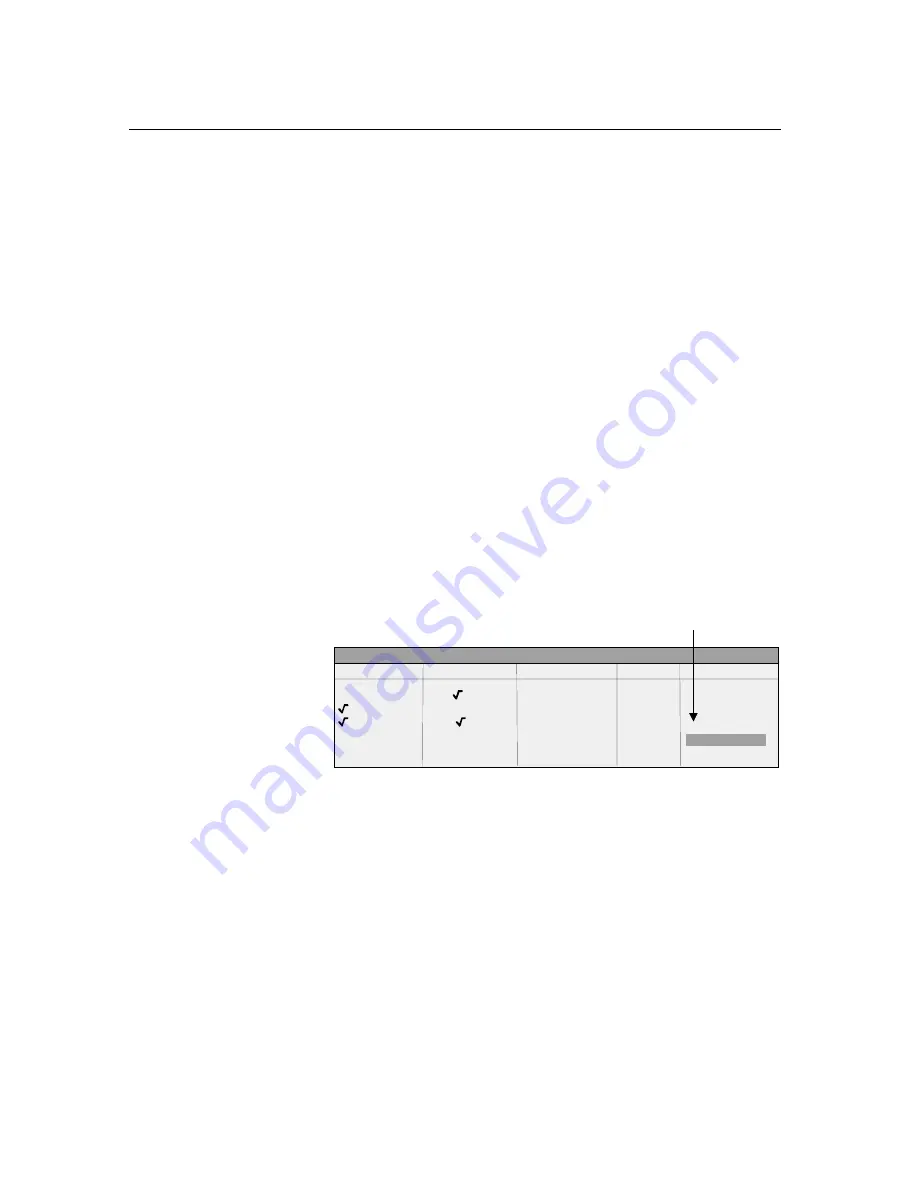
2. Selection of the parameter
NAME COMPATIBLE LIMIT CHECK TRACE MARGIN
GSM22UP off 1 0 dB
LP1GHz on 2 0 dB
LP1GHz off 1 0 dB
MIL461A off 2
-10 dB
LIMIT LINES
marking cursor
Selection of the par ameter (or the s etting) is made using the
marking cursor.
¾
Press the cursor keys to move to the wanted field.
or
¾
Rotate the spinwheel until the wanted field is marked. The cursor
keys are used to specify the direction of the spinwheel movement
(horizontal or vertical)
When shifting the cursor, elements may be s kipped which can
not be edited. Table elements, which can not be s elected are
indicated by a different color.
Summary of Contents for FSMR series
Page 1: ...R S FSMR Measuring Receiver Getting Started Test Measurement Getting Started 1313 9698 02 03 ...
Page 7: ......
Page 9: ......
Page 11: ...Contents Preparing for Operation R S FSMR 1313 9723 12 I 1 2 E 1 Fig 1 1 Front View ...
Page 13: ...Front View R S FSMR 1313 9723 12 1 2 E 2 Fig 1 1 Front View ...
Page 15: ...Front View R S FSMR 1313 9723 12 1 4 E 2 Fig 1 1 Front View ...
Page 17: ...Front View R S FSMR 1313 9723 12 1 6 E 2 Fig 1 1 Front View ...
Page 19: ...Front View R S FSMR 1313 9723 12 1 8 E 2 Fig 1 1 Front View ...
Page 51: ......
Page 71: ......
Page 102: ...R S FSMR Menu Overview 1166 3363 12 3 29 E 3 AMPT Key ...
Page 107: ...Menu Overview R S FSMR 1166 3363 12 3 34 E 3 DEMOD Key ...
Page 108: ...R S FSMR Menu Overview 1166 3363 12 3 35 E 3 AUDIO Key ...
Page 111: ...Menu Overview R S FSMR 1166 3363 12 3 38 E 3 AMPT Key ...
Page 112: ...R S FSMR Menu Overview 1166 3363 12 3 39 E 3 MEAS Key ...
Page 113: ...Menu Overview R S FSMR 1166 3363 12 3 40 E 3 ...
Page 114: ...R S FSMR Menu Overview 1166 3363 12 3 41 E 3 BW Key ...
Page 116: ...R S FSMR Menu Overview 1166 3363 12 3 43 E 3 Menu Overview another Keys MKR Key ...
Page 120: ...R S FSMR Menu Overview 1166 3363 12 3 47 E 3 TRACE Key ...
Page 123: ...Menu Overview R S FSMR 1166 3363 12 3 50 E 3 FILE Key ...
Page 125: ...Menu Overview R S FSMR 1166 3363 12 3 52 E 3 SETUP Key ...
Page 127: ...Menu Overview R S FSMR 1166 3363 12 3 54 E 3 LOCAL Menu LOCAL ...
Page 128: ...R S FSMR Menu Overview 1166 3363 12 3 55 E 3 Menu Overview Ext Generator Control ...


