


R&S FSMR
Menu Overview
1166.3363.12
3.45
E-3
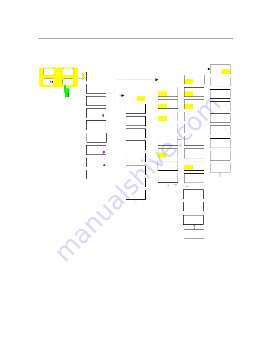
MKR FCTN Key
REF POINT
LEVEL
NDB DOWN
PH NOISE
ON OFF
MARKER
DEMOD
MKR
MKR
SELECT
MARKER
PHASE
NOISE
SHAPE FACT
60:3 60:6
MRK->TRACE
AMPT
SPAN
PEAK
REF POINT
LVL OFFSET
REF POINT
FREQUENCY
MKR
STOP TIME
AM
FM
FCTN
MKR DEMOD
ON OFF
CONT
DEMOD
NOISE MEAS
PEAK
SEARCH
NEW
SEARCH
SORT MODE
FREQ LEVEL
PEAK
LIST
PEAK
EXCURSION
LEFT
LIMIT
RIGHT
LIMIT
PAGE UP
AUTO PEAK
SEARCH
SQUELCH
PEAK LIST
EXPORT
DECIM SEP
.
,
PEAK LIST
ON OFF
AUTOSEARCH
ON
OFF
PAGE DOWN
MKR SYMBOL
ON OFF
SEARCH
LIMITS
MKR SYMBOL
ON OFF
MKR NUMBER
ON OFF
MKR PEAK
CONT (50)
THRESHOLD
SEARCH LIM
OFF
Summary of Contents for FSMR series
Page 1: ...R S FSMR Measuring Receiver Getting Started Test Measurement Getting Started 1313 9698 02 03 ...
Page 7: ......
Page 9: ......
Page 11: ...Contents Preparing for Operation R S FSMR 1313 9723 12 I 1 2 E 1 Fig 1 1 Front View ...
Page 13: ...Front View R S FSMR 1313 9723 12 1 2 E 2 Fig 1 1 Front View ...
Page 15: ...Front View R S FSMR 1313 9723 12 1 4 E 2 Fig 1 1 Front View ...
Page 17: ...Front View R S FSMR 1313 9723 12 1 6 E 2 Fig 1 1 Front View ...
Page 19: ...Front View R S FSMR 1313 9723 12 1 8 E 2 Fig 1 1 Front View ...
Page 51: ......
Page 71: ......
Page 102: ...R S FSMR Menu Overview 1166 3363 12 3 29 E 3 AMPT Key ...
Page 107: ...Menu Overview R S FSMR 1166 3363 12 3 34 E 3 DEMOD Key ...
Page 108: ...R S FSMR Menu Overview 1166 3363 12 3 35 E 3 AUDIO Key ...
Page 111: ...Menu Overview R S FSMR 1166 3363 12 3 38 E 3 AMPT Key ...
Page 112: ...R S FSMR Menu Overview 1166 3363 12 3 39 E 3 MEAS Key ...
Page 113: ...Menu Overview R S FSMR 1166 3363 12 3 40 E 3 ...
Page 114: ...R S FSMR Menu Overview 1166 3363 12 3 41 E 3 BW Key ...
Page 116: ...R S FSMR Menu Overview 1166 3363 12 3 43 E 3 Menu Overview another Keys MKR Key ...
Page 120: ...R S FSMR Menu Overview 1166 3363 12 3 47 E 3 TRACE Key ...
Page 123: ...Menu Overview R S FSMR 1166 3363 12 3 50 E 3 FILE Key ...
Page 125: ...Menu Overview R S FSMR 1166 3363 12 3 52 E 3 SETUP Key ...
Page 127: ...Menu Overview R S FSMR 1166 3363 12 3 54 E 3 LOCAL Menu LOCAL ...
Page 128: ...R S FSMR Menu Overview 1166 3363 12 3 55 E 3 Menu Overview Ext Generator Control ...


