background image


#WVQ


#WVQ


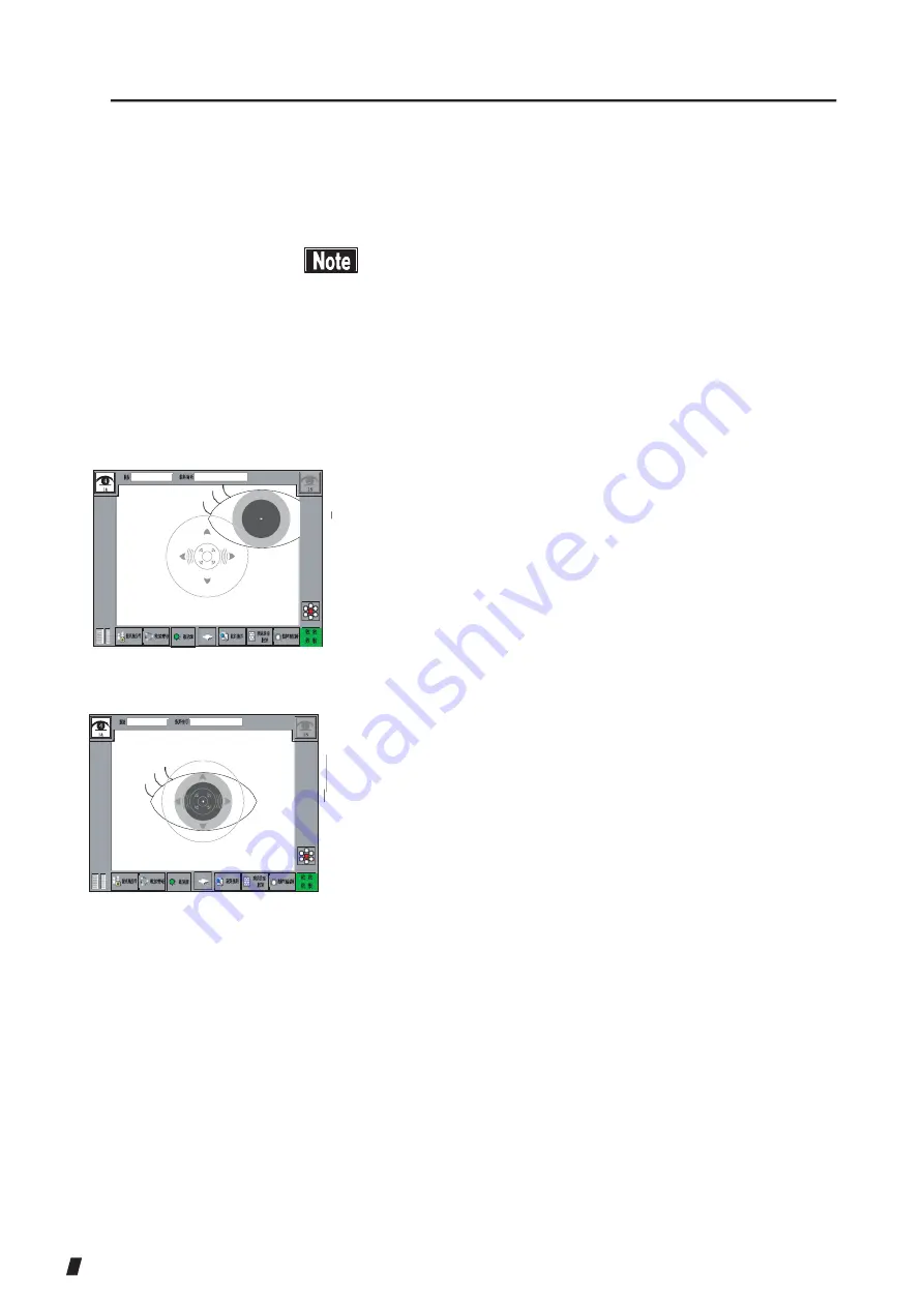
4)  When the focus indicator (4) appears on the screen, 

focusing in the Y axis automatically starts.


<Positioning by the joystick>


(1)


n


The auto mode is the normal way to capture more 
precise  images  with  this  instrument.  However, 
auto  alignment  may  not  work  properly  if  there  is 
not  adequate  reflection  due  to  corneal  disorders, 
etc. If this happens, use manual mode instead.


n


If  the  patient  is  suffering  from  severe  cornea 
opacity, the endothelial image may not be captured 
even using manual mode.


1)  Operate  the  joystick  so  the  center  of  the  cornea  (1) 

enters  the  target  ring  (3).  The  target  center-point  (2) 
appears. (Refer to “2.4 Operation of the joystick.”)


(Fig. 1)


(3)


(2)


(4)


2)  Move the joystick back and forth to move the head unit 

so the focus indicator (4) on the screen becomes small.


When the focus indicator (4) is shown horizontally, 
the head unit is too far from the eye; when the focus 
indicator  is  shown  vertically,  the  head  unit  is  too 
close to the eye.


3)  When the focus indicator (4) does not appear, align the 

focus with the target center-point (2) or the iris.


(Fig. 2) 

(5)


3-12


Summary of Contents for REM 3000

Page 1: ...ensure correct and safe operation If you have questions about operations please contact RODENSTOCK or our local distributor Always follow the operation procedures described in this manual Keep this manual in a readily available location while operating the instrument Contact our local distributor if you lose this instruction manual ...

Page 2: ......

Page 3: ...instrument before servicing the instrument Otherwise you may get an electric shock n Do not place water or chemicals on the instrument Any water or chemicals entering the instrument may cause an electric shock or failure n Only use the specified terminal for connection of the instrument Using another type of terminal may result in failure of the instrument n This instrument is a diagnostic measuri...

Page 4: ... labels provided for the instrument to become illegible A caution label is provided on the back side of the instrument n If a label is damaged or becomes illegible please contact RODENSTOCK or our local distributor i 2 Caution label ...

Page 5: ...escribes information required for installing and using the instrument 4 TECHNICAL INFORMATION Describes useful technical information about the instrument 5 INSPECTION AND MAINTENANCE Describes procedures for replacing consumable parts etc that the user of the instrument should normally conduct 6 TROUBLESHOOTING Describes how to solve problems 7 CONSUMABLES AND OPTIONAL EQUIPMENT Describes consumab...

Page 6: ...if unheeded could result in a hazardous situation where there is a possibility of serious injury or death n This is a precaution that if unheeded may result in a situation where there is a possibility of minor or moderate injury or damage to property n This is an additional instruction which may contain a special precaution on company policy related either directly or indirectly to the safety of p...

Page 7: ...ERATION PROCEDURES 3 1 3 1 Installation 3 1 3 1 1 Precautions for installing the instrument 3 1 3 1 2 Precautions for connecting the power cord 3 2 3 2 Preparation before use 3 3 3 2 1 Connecting the power cord 3 3 3 2 2 Connecting an external digital printer 3 3 3 2 3 Connecting external ID input device 3 4 3 2 4 Connecting DATA Transfer 3 4 3 2 5 Starting 3 5 3 2 6 Setting 3 5 3 3 Capturing Imag...

Page 8: ...3 6 4 Export 3 38 3 6 5 LAN 3 40 3 6 6 Information 3 41 4 TECHNICAL INFORMATION 4 1 5 INSPECTION AND MAINTENANCE 5 1 5 1 Warranty 5 1 5 2 Durable years 5 2 5 3 Inspection 5 2 5 4 Routine maintenance 5 3 5 4 1 Forehead pad Chin rest 5 3 5 4 2 Outer surface 5 3 5 5 Replacing consumables 5 4 5 5 1 Fuses 5 4 5 5 2 Chin rest paper 5 4 5 6 Storing 5 5 5 7 Disposal 5 6 6 TROUBLESHOOTING 6 1 7 CONSUMABLES...

Page 9: ...8 3 Operating environment 8 2 8 4 Classification 8 3 8 5 Declaration of conformity with EMC 8 3 9 INDEX 9 1 iii 3 ...

Page 10: ...This page is intentionally blank iii 4 ...

Page 11: ...e and allowable current or power consumption of the power source Operating the instrument connected to an inappropriate power source may cause fire or an electric shock Connect the power plug to a grounded 3P outlet Otherwise a short circuit due to failure of the instrument may result in an electric shock Do not place any heavy object on the power cord or squash the power cord Connecting such a de...

Page 12: ...Peel off the top sheet of chin rest paper and clean the forehead pad with a cloth dampened with alcohol before capturing Check that the instrument is correctly grounded Check that the date set in the instrument conforms to the actual operation date and time When the room temperature lowers to 10 C or below in winter turn the instrument on and warm it up before starting operation Low temperature ma...

Page 13: ...r capture a new image When using the photographing and analysis results by this instrument for diagnosis also conduct other examinations and carefully consider the results of those examinations to make final judgment Capturing conditions may affect the precision of captured images or analysis results Do not use the corneal thickness and ultrasonic correction for corneal thickness output from this ...

Page 14: ...ailure of the instrument The instrument contains high voltage sections Touching these sections will result in death or serious injuries Disconnect the power plug from the outlet when replacing fuses Otherwise you may get an electric shock resulting in death or serious injuries Use the power cord and fuses provided with the instrument or specified by RODENSTOCK to ensure safety Also do not use the ...

Page 15: ...sporting the instrument n When taking the instrument out of the box pull the outer box upward and then remove the packing materials Be careful not to lift the instrument by directly holding the head unit chin rest forehead pad or joystick Otherwise the instrument could be damaged Main unit 1 Power code 1 Fuses 2 fuses are installed in the main unit 4 Chin rest paper 1 Pins for Chin rest paper 2 Du...

Page 16: ... represented as the number of cells per 1 mm2 DATA Transfer System that outputs the examination data from RODENSTOCK products to digital files Dark Area Black circle area to be observed by the specula microscope L count Method where the physician performs analytical calculation by selecting cells on the screen MA Manual Alignment Refer to Manual Alignment Max Indicates the dimension of the largest...

Page 17: ...ight in up down right left focus directions Auto Shot Function that automatically starts measurement when the patient s eyes are within the measuring range Auto Power Off Function that automatically turns the LCD off with only the power lamp flashing when the instrument is not operated for the specified time Auto Power Off mode Touch any button to return to Normal mode Touch Alignment Allows you t...

Page 18: ...e physician observes the patient s eye on the monitor screen and roughly aligns the capturing position fine alignment and capturing are automatically conducted When the endothelial cells cannot be captured automatically align the capturing position with the joystick and press the joystick button to start capturing Once the capturing process begins a green LED will shine on the patient s eye and a ...

Page 19: ...ays the capturing screen and various setting screens Touch the touch panel buttons shown on the monitor to make various settings and operate the instrument 3 Joystick Tilting the joystick to the right left back and forth moves the head unit to the right left forward and backward for fine positioning 4 Joystick button Starts capturing images 2 1 ...

Page 20: ...ta 10 MODE switch Switches the alignment mode between automatic and manual 11 PRINT switch Prints the captured result on a connected external printer 12 ANALYSIS switch Analyzes the captured endothelial image automatically 13 Link switch Connects to the external devices to send data 14 PACKING switch Pressing this button for 3 seconds moves the head unit to the lowest position for packing lower de...

Page 21: ... 19 LAN connector Connect the LAN cable here 20 Maintenance switch This switch is reserved for use by servicemen performing maintenance work Do not operate this switch 2 3 ...

Page 22: ...ery is being captured the patient is prompted to stare at the peripheral sight fixing lamp 3 Chin rest The patient places their chin on this rest 4 Forehead pad The patient presses their forehead against this pad 5 Power switch Press the I or O side to turn the instrument on or off respectively 6 Power socket Connect the power cord here 7 Fuse holder Insert the fuses here 2 4 4 1 3 6 5 7 ...

Page 23: ...ing the eye to be examined 2 ID number ID Displays the ID number 3 Patient s name Name Indicates the patient s name 4 Chin rest height Displays the current chin rest height according to the preset 6 levels 5 Head unit height Displays the current head unit height according to the preset 11 levels 6 Setup button Sets operation conditions for each function 7 Mode button Switches the alignment mode be...

Page 24: ...button is pushed in manual mode viewing a zoom in endothelial image 13 Sight fixing button Displays the currently set position of the sight fixing lamp Push this button to select the position of the sight fixing lamp 14 Target ring Index reference used when aligning the patient s eye position for capturing the image When Touch Alignment is ON the head unit moves toward the eye while this icon is p...

Page 25: ...worst 3 Area button Manually specifies the area to be analyzed from the captured image When performing analytical calculation using the L count function touch the Area button and the L count button appears 4 Tone button Adjusts brightness for displaying captured endothelium images 5 Anterior eye segment image display Displays the captured anterior eye segment image 6 Sight fixing lamp position dis...

Page 26: ...2 7 ...

Page 27: ... be analyzed out of the 15 captured images 12 Retake button Retakes the images In that case the currently displayed image will not be saved This button does not appear in Quick mode 13 CLEAR button Deletes all the examination data when held down 14 Measured corneal thickness and ultrasonic correction for corneal thickness CCT Measured corneal thickness CCT US The reference value expected when meas...

Page 28: ... 533 㱘㫄 24 00 1 525 525 55 55 205 205 420 420 30 30 94 94 313 313 3195 325 325 15 Analytical result screen Standard mode 300 400 60 6 60 400 500 20 7 20 500 600 10 8 10 600 700 9 700 800 10 800 900 14 15 16 17 18 19 26 20 Analytical result screen Standard mode 25 1 2 3 4 22 5 6 22 7 8 1 25 10 21 15 14 19 20 14 16 ...

Page 29: ...2 9 ...

Page 30: ... Displays the raw endothelial image 3 Trace button Displays the extracted edges 4 Display by dimension button According to the analysis result each cell dimension is color coded and displayed 5 Display by shape button According to the analysis result each shape is color coded and displayed 6 Enlarge and Reduce buttons Enlarges or reduces the size of the displayed image 7 Move button Moves the disp...

Page 31: ...2 10 ...

Page 32: ...ally 15 PRINT button Prints the captured result on a connected external printer 16 Export button Connects to the external devices to send data 17 Data button Recalls the data saved in the memory 18 Select button Returns to the captured image selection screen where you can select other images 19 Next Eye button Moves to the capturing of the next image The currently captured images will be saved to ...

Page 33: ...t image 24 Dual button Switches the screen from the one eye result display screen in Quick mode to the both eye result display screen 25 R L display switching button In Quick mode not only displays the images of both the right R and left L eyes but also moves the one eye analytical result screen when the button is pressed 26 Dark Area button Automatically analyzes the dark area and opens the Dark ...

Page 34: ...e the hand rest 1 in the direction the head unit is to be moved The further you slide the rest the faster the head moves Up and down Slide the up down ring 2 in the direction the head unit is to be moved Fine operation Forward backward right and left Tilt the joystick in the direction the head unit is to be moved Fig 2 Up and down Turn the up down ring 2 Clockwise Raises the head unit Counterclock...

Page 35: ...y without pressing the panel continuously n Do not press hard against the touch panel or with a sharp edged object Otherwise the panel may be damaged 1 Up and down right and left When directly touching the panel the head unit moves so the touched point moves to the center Touch the point where the center of the pupil 1 is shown The pupil center 1 moves to the center of the screen Fig 1 2 Forward b...

Page 36: ...d the head unit chin rest forehead pad or joystick when lifting the instrument These components are detachable and the instrument may drop resulting in injuries n Install the instrument in a location not subject to direct sunlight high temperature and humidity or air with significant dust salt and or sulfur content These may cause failure or malfunction of the instrument n Install the instrument i...

Page 37: ...wer cord This may cause fire or an electric shock n Completely insert the power plug into the outlet Faulty contact allowing any metal to contact exposed plug terminals or dust accumulated on exposed plug terminals may result in fire or an electric shock n Check the frequency voltage and allowable current or power consumption of the power source Operating the instrument connected to an inappropria...

Page 38: ...on of the power cord is shown Make sure that the orientation is correct and that the cord is firmly plugged in n Use only the specified printer and cables Use a printer in conformity with IEC60601 1 or a printer meeting IEC950 and isolated with an insulation transformer to avoid possibilities of electrical shock Fig 1 2 1 For a Mitsubishi digital printer plug the connector into the USB H terminal ...

Page 39: ...3 3 ...

Page 40: ...wn Make sure that theorientation is correct and that the cord is firmly plugged in n The instrument is not provided with optional cables Provide optional cables A LAN cable is required to connect to DATA Transfer a Connecting LAN cables For connection to DATA transfer on a LAN the type of LAN cables used varies depending on the method of connection Provide the following type of LAN cables dependin...

Page 41: ...ument is on and the LAN connection is established Turn on the power switch 1 The power lamp lights and the title screen appears The head unit also moves to its initial position Fig 1 OFF 3 2 6 Setting Refer to 3 6 Settings and set the capturing conditions 3 5 ...

Page 42: ...nformation with the touch panel 1 2 1 By touching the ID field 1 or Name field 2 on the top of each screen the patient information entry screen Fig 2 is displayed Enter ID number and patient s name as necessary Fig 1 Fig 2 6 7 1 2 3 4 5 2 Touch the ID field 1 Name field 2 Date of Birth field 3 or Physician field 5 The alphabetic keypad appears Enter the ID patient s name date of birth and physicia...

Page 43: ... entry screen is displayed 1 If an ID number is entered using an external ID input device on the patient information entry screen Fig 1 the entered ID appears Fig 1 1 2 2 After the patient information is entered touch the OK button 1 to apply the entered information and return to the capturing screen Touch the Cancel button 2 to clear the entered information and return to the capturing screen 3 7 ...

Page 44: ... alphabetic entry mode Num button Switches to numeric entry mode A Z 0 9 buttons Registers characters and numbers in the input field CLEAR button Deletes what is entered in the input field BS button Deletes a character from what has been entered del button Deletes a character from what has been entered Numeric keyboard TEXT Apply 1 2 3 Close 4 5 6 7 8 9 Clear 0 BS Fig 3 TEXT field Displays what ha...

Page 45: ...rest so that the patient feels comfortable using thisinstrument n Peel off the top sheet of chin rest paper and clean the forehead pad and capturing window with a cloth dampened with alcohol before the next patient 2 3 4 1 1 Have the patient place their face on the chin rest 1 Adjust the chin rest height so that the height of the corner of the eye is aligned with eye level mark 2 Touch the CHIN RE...

Page 46: ...3 9 ...

Page 47: ...nter of the pupil is captured However the position of the sight fixing lamp can be changed to 6 other positions when a normal capture is not possible or when a different area is to be captured Press the sight fixing lamp button 1 on the capturing screen to display seven types of the sight fixing lamp buttons 2 Fig 2 A red dot shows the position of a sight fixing lamp Press any of the sight fixing ...

Page 48: ...ong direction or moves the image capture may not be correctly conducted Positioning by Touch Alignment n When moving an element using the touch panel touch the panel and release your finger immediately without pressing the panel continuously 1 Use Touch Alignment or the joystick to position the Fig 1 Fig 2 5 1 3 2 4 patient s eye on the screen 2 Lightly touch the center of cornea 1 on the screen T...

Page 49: ...ty the endothelial image may not be captured even using manual mode 1 Operate the joystick so the center of the cornea 1 enters the target ring 3 The target center point 2 appears Refer to 2 4 Operation of the joystick Fig 1 3 2 4 2 Move the joystick back and forth to move the head unit so the focus indicator 4 on the screen becomes small When the focus indicator 4 is shown horizontally the head u...

Page 50: ... to ensure accurate alignment in manual mode resulting in frequent capturing errors a Selecting auto and manual modes Press the Mode button 1 on the capturing screen to select the auto mode or manual mode Touch the AA AS AA MS or MA MS button 2 to select the appropriate mode AA AS Auto Alignment Auto Shot AA MS Auto Alignment Manual Shot MA MS Manual Alignment Manual Shot The selected mode will be...

Page 51: ...age of an endothelium Press the joystick button 1 again to start the capturing process Pressing the Zoom In button 2 and the Capture button 3 in the capturing screen will also start the capturing process too If a corneal endothelium image disappears from a zoom in image of an endothelium pressing the Zoom Out button in the capturing screen to return to an anterior eye segment image Perform the ali...

Page 52: ... the image again Refer to 3 3 4 Changing sight fixing lamp position Eyelid or eyelash is on the alignment ring Ask the patient to open her eyes wide or have the physician lightly hold the patient s upper eyelid and try the capturing process again e Adjusting the intensity of the illuminating light Press the illuminating light adjustment button 1 to set the brightness of the illuminating light to H...

Page 53: ... set and specify a frame of 100µm around when 100µm is set Keep touching the Area button for a while to select the entire area of the captured image again Touching the Area button on the captured image selection screen allows you to perform analytical calculation using the L count function Refer to 3 3 10 Analytical calculation using the L count function for the L count operation procedure Tone bu...

Page 54: ...l thickness and ultrasonic correction for corneal thickness 8 CCT Measured corneal thickness CCT US The reference value expected when measuring the same corneal thickness using our ultrasonic pachymeter SP 100 etc This item can be set to be displayed or hidden Refer to 3 6 2 Function Print button 9 Prints the captured result on a connected external printer Next Eye button 10 The analyzed image wil...

Page 55: ... Pressing the ANALYSIS button 13 PRINT button 14 and CLEAR button 15 on the membrane button panel performs the same operation as the Analysis button 5 Print button 9 and Clear button 12 respectively 13 Fig 3 ...

Page 56: ...3 18 ...

Page 57: ...21 7 10 1 24 Fig 1 b Both eye display in Quick mode 㪠㪛 㪥㪸㫄㪼 4 07 12 24 24 00 1 㪧㪿㫆㫋㫆 㪫㫉㪸㪺㪼 㱘㫄㪉 㪍 325 㪥㪬㪤 3195 㪚 㪛 313 㪘㪭㪞 325 3195 313 15 9 Photo button 2 Displays the raw endothelial image Trace button 3 525 㪚 㪚 㪫 525 22 㪧㫉㫀㫅㫋 㪜㪻㫀㫋 㪩 㪜㫏㫇㫆㫉㫋 㪜㪻㫀㫋 㪣 Displays trace lines of extracted endothelium tissue in red 㪥㪼㫏㫋 㪜㫐㪼 㪚㫃㪼㪸㫉 Edges are not displayed when analytical calculation is 12 11 16 17 11 13 per...

Page 58: ...ution by the plemorphism 20 Color coded are not displayed when analytical calculation is performed using the L count function Enlarge and Reduce buttons 6 While an endothelial image is zoomed in touching the on screen endothelial image after pressing this button can zoom the endothelial image in or out the on 3 19 ...

Page 59: ...e analyzed endothelial cells number of cells per 1 mm2 AVG The average dimension of the analyzed endothelial cells SD The standard deviation of the analyzed endothelial cell dimensions CV The coefficient of variation of the analyzed endothelial cells derived by dividing the average dimension by the standarddeviation Max The dimension of the largest analyzed endothelial cell Min The dimension of th...

Page 60: ...pressing this button starts the analytical calculation and displays the analytical calculation results 9 Edit Edit R Edit L button 11 Edits the automatically extracted edges of endothelial cells in manual mode Refer to 3 3 9 Editing the extracted edges Touch the Edit R and Edit L buttons to move to the edit screen of the right and left eyes respectively Print button 12 Prints the captured result o...

Page 61: ...liability mark 21 The reliability level for automatic analysis is automatically determined and displayed on the screen Refer to 3 3 11 Displaying reliability Corneal thickness measurement 22 Displays the measured corneal thickness data Anterior eye segment image 23 Displays a captured anterior eye segment image R L display switch button 24 In Quick mode not only displays the images of boththe righ...

Page 62: ...area Max Largest area of tissue among all analyzed 㪘㫅㪸㫃㫐㫊㫀㫊 CPEGN 15 6 8 9 7 16 Fig 2 a Standard mode 2 dark areas Min Smallest area of tissue among all analyzed dark areas Ratio Ratio of the dark area size relative to the total area The total area is the sum of 5 4 1 㪧㪿㫆㫋㫆 㪫㫉㪸㪺㪼 㱘 㫄 㪉 㪠㪛 07 12 24 24 00 㪛㪸㫉㫂 㪘㫉㪼㪸 㪘㫅㪸㫃㫐㫊㫀㫊 3 Edit button 6 analyzed dark area and the area of analyzed endothelium tiss...

Page 63: ... 4 O p e n s t h e e d i t s c r e e n E d i t b u t t o n 7 O p e n s t h e a n a l y s i s r e s u l t s creen Fig 1 ...

Page 64: ...3 23 ...

Page 65: ...time deletes all trace lines of endothelium tissue and dark areas currently displayed and then displays trace lines of Fig 1 c One eye result display in Quick mode 4 2 3 5 automatically extracted endothelium tissue and dark areas All Clear button 7 㪠㪛 㪥㪸㫄㪼 4 1 07 12 24 24 00 Holding this button for an extended time deletes all 14 㪘㫉㪼㪸 㪫㫆㫅㪼 㪘㫌㫋㫆 㪘㪣㪣 㪧㪿㫆㫋㫆 㪫㫉㪸㪺㪼 㱘㫄㪉 㪍 10 11 12 13 17 trace lines of e...

Page 66: ... 15 6 Fig 2 3 24 8 9 7 16 Redo button 9 ...

Page 67: ...d specify a frame of 100µm around when 100µm is set Keep touching the Area button for a while to select the entire area of the captured image again Analysis button 15 Performs analytical calculations of edited edge lines and returns to the analysis result screen Returns to the Dark Area Analysis screen when the dark area button is activated Cancel button 16 Returns to the analysis result screen wi...

Page 68: ...nd the Counted cells display field 3 Eraser button 4 Undo button 5 and Redo button 6 are displayed Fig 2 Analytical domain Fig 3 3 Specify an area to be analyzed by selecting two opposing points in an area where the shape of the cells can be confirmed Specified by a 100µm sided frame when 100µm is set Touch all cells in the specified area one at a time with stylus pen Check that orange points appe...

Page 69: ...nalyzed Eraser button 4 Todelete the orange points on touched cells touch the Eraser button 4 and then touch the points to be deleted These are deleted and the value in the Counted cells display field decreases accordingly To select the cells again touch the Eraser button 4 again The status returns to the cell selection mode Undo button 5 Cancels cell selection operations by touching the screen on...

Page 70: ...e resultant reliability is slightly lower E Because the range of captured cells issmall and visibility of captured images is poor cell outlines are not extracted correctly by automatic analysis and the resultant reliability is low When e or E is displayed perform any of the following actions according to the captured image condition n Touch the Select button to return to the captured image selecti...

Page 71: ...325 313 94 30 420 205 55 525 The reliability mark does not appear when the following analytical calculations are conducted n Analytial calculation using the selection release button n Editing cell outlines using the Edit Edit R Edit L button n Analysis using the L count function 㪘㪭㪞 㪪 㪛 㪚 㪭 㪤㪸㫏 㪤㫀㫅 㪚㪚㪫 㪘㫉㪼㪸 㩿㪧 ǴO2 0 1 100 2 200 300 400 500 600 700 800 900 㪜㪻㫀㫋 㪧㫉㫀㫅㫋 㪜㫏㫇㫆㫉㫋 㪛㪸㫋㪸 㪪㪼㫃 Fig 1 3 29 㪧㪿㫆㫋...

Page 72: ...ge on the touch panel and touch the Analysis button 2 to display the analysis result screen Fig 2 Print button 3 Prints the displayed image on a connected external printer Fig 2 1 Export button 4 Select an image on the touch panel and touch the Export button to send the data to external equipment Refer to 3 5 1 Sending examination data Next Eye button 5 Displays the captured image Delete button 6 ...

Page 73: ... may be processed as the data of another patient n For data communication it is advisable to enter an ID number Data can be sent without an ID number entered However it is possible that the patient s data in question cannot located within all the examination data being put out from DATA Transfer If data is sent without an ID number being entered check the examination data immediately after it has ...

Page 74: ...a previous screen Press the Cancel button 5 to return to a previous screen without anything confirmed Pressing the CLEAR switch 6 of the membrane switch Fig 1 erases all patient information and captured data and displays a capturing screen 3 When the data are sent normally COMPLETE message is displayed and the display returns to the previous screen 2 Fig 3 3 4 5 Fig 4 3 32 520 㱘㫄 533 㱘㫄 ǴO2 900 ...

Page 75: ...lect the setting item and set conditions as needed on the corresponding screen Touch the return icon 3 after setting is complete to return to the previous screen Touch the Save Exit button 4 to save the new settings and return to the capturing screen Fig 1 Touching the Cancel button 5 returns you to the capturing screen without changing any settings 3 2 Fig 2 4 5 Common Items related to operationa...

Page 76: ...zer setting 2 ON Enables the buzzer sound OFF Disables the buzzersound Fig 2 6 Time Adjust 3 Sets the current date and time Touch the Setting button 4 The Time Adjust screen Fig 2 appears Touching any of the date time fields 5 displays the keypad Fig 3 for you to change the setting After adjusting the date and time touch the Set button 6 to save the setting and return to the previous screen Fig 1 ...

Page 77: ...ry Image setting 2 Sets the image display immediately after analysis Photo Displays an endothelial image Trace Displays an image for tracing µm2 Displays an image with the cell size color coded 6 Displays an image with the cell shape color coded Dark Area setting 3 ON Includes the dark area in the calculation for analyzing endothelium tissue OFF Does not include the dark area in the calculation fo...

Page 78: ...rection value for corneal thickness When CCT US Display 4 is set to ON the setting button is displayed Default 13µm Setting range 0 3µm Reliability 7 ON Displays Reliability mark OFF Reliability mark is not displayed Lcount Assist 8 Sets whether to roughly select cells in advance automatically when executing the L count function ON Automatically selects and displays cells OFF Does not select cells...

Page 79: ...00D or CP30D is connected to the instrument P93D P95D Selected when a digital monochrom printer P93D or P95D is connected to the instrument The size of printing can be chosen when choosing the button Small Large Fig 2 PictBridge Selected when a PictBridge compliant printer is connected to the instrument 3 37 Large Print Print ...

Page 80: ... an ID be entered Unless the ID is entered the data cannot be sent Basically This is set when enabling the data to be sent without an ID normally an ID must be set If an ID is not entered the data will be sent as NO ID Rarely Set when you do not want to be concerned aboutIDentry Thesendconfirmationscreen will be displayed but the measured data will besentautomatically IfanIDisnotentered the data w...

Page 81: ...umber of digits for the ID 1 64 digits when an ID is entered from a bar code Host IP Setting Type 8 This setting enables you to select an IP address or computer name when specifying the host computer Address Specifies the host computer with the IP address 9 DNS Specifiesthehostcomputerwiththecomputer name 10 Touse DNS a DNS server must be running on the LANenvironment Host IP Address 9 Specified w...

Page 82: ...on Connect Shows that it is connected Check LAN Cable Shows that it is disconnected Even when this is displayed the connection test will be continued for 60 seconds Server not found Cannot communicate with the server PC software n If only this instrument and a computer receiving DATA Transfer are connected to the network they can be set as follows 1 Checking the computer s IP address Check and not...

Page 83: ...255 255 255 0 255 255 255 0 Check the DATA Transfer screen Same value as the computer Default gateway 0 0 0 0 All 0s Server IP address 192 168 2 128 Computer s IP address 1 Any number between 1 to 255 except the number used by the computer In this example 128 3 6 6 Information Displays the product information Touch the product name display field 1 to display the alphabetic keyboard and enter the n...

Page 84: ...This page is intentionally blank 3 42 ...

Page 85: ...r invalid and the dimensions and shapes of valid cells are calculated Ultrasonic Correction for Corneal Thickness The following shows the result of comparison between the corneal thickness of 120 normal eye samples with no corneal diseases or corneal transplants measured by this instrument and that measured by TOMEY ultrasonic pachymeter SP 100 4 1 ...

Page 86: ...This page is intentionally blank 4 2 ...

Page 87: ...for proper installation use and maintenance of product This warranty is only applicable to the new product and DOES NOT cover any damage resulting from or caused by accident or negligence abuse misuse mishandling improper modification of this product by persons other than personnel duty authorized by Tomey not to a product whose serial number or batch number is removed altered or effaced THIS WARR...

Page 88: ...urable for 8 years when operated under the appropriate environment and adequately inspected and serviced n Good endothelial images may not be obtained if the instrument has any defects Contact our local distributor or RODENSTOCK for necessary repairs as soon as possible ...

Page 89: ...5 2 ...

Page 90: ...ch as the capturing window are not exposed to dust fingerprints etc Otherwise the capturing accuracy will be deteriorate n Place the dust cover over the main unit when not being used 5 4 1 Forehead pad Chin rest 5 4 2 Outer surface n Gently wipe the sections that patients directly touch such as the forehead pad or chin rest with a soft cloth dampened with alcohol before starting measurement for a ...

Page 91: ...blem Turn off the instrument immediately and contact our local distributor 1 Turn power off 2 Disconnect the power cord from the outlet Fig 1 3 Insert a coin or similar in the slot on the fuse case located at the bottom of the main unit Turn the screw counterclockwise to remove it 4 Replace the blown fuse with a new one 5 Reverse the procedure above to install the fuse holder 5 5 2 Chin rest paper...

Page 92: ...e the instrument in a location not subject to direct sunlight high temperatures and humidity or air with significant dust salt and or sulfur content These may cause failure or malfunction of the instrument n Store the instrument in a level and stable location free of vibration and mechanical impacts to ensure correct capturing and prevent the instrument from falling or being dropped which can resu...

Page 93: ...als for use when moving or transporting the instrument n Keep the packing materials and the box together n When disposing of the packing materials sort them by type and disposed them as directed by relevant laws and local rules and regulations 5 6 ...

Page 94: ...en after checking the applicable item listed below contact our local distributor The power lamp or monitor does not turn on when the power switch is turned on Faulty power plug Check that the power plug is firmly connected to the instrument and power outlet Check that the power cord is not cracked torn etc Power not supplied Check that power is supplied to the power outlet to which the power cord ...

Page 95: ...ternal functions of the instrument Stop using the instrument and contact our local distributor The error message Calender Clock Error is displayed There are problems with the date clock function Contact our local distributor The error message Chin Rest Error is displayed There are problems with the chin rest elevator Contact our local distributor The error message Joy Stick Error is displayed Ther...

Page 96: ...is displayed Poor cable connection Check t he cables connected t o the instrument and the other ends connected to other instruments DATA Transfer is not running Check that DATA Transfer including the relay software when being connected via USB is running correctly Refer to the instruction manual of DATA Transfer for details There may be an error in DATA Transfer Check that there is no error in DAT...

Page 97: ...T he HUB is not t urned on W hen connected to a LAN Turn on the HUB The settings for the instrument and DATA Transfer are not correct Refer to 3 6 4 Export and make settings properly 6 4 ...

Page 98: ...7 CONSUMABLES Contact our local distributor to order any of the following consumables Chin rest paper 100 sheets set Fuse Specify the fuse type as Fuse for REM 3000 7 1 ...

Page 99: ...This page is intentionally blank 7 2 ...

Page 100: ...m 8 1 3 Main unit Stroke of moving section 88 mm X axis 40 mm Y axis 50 mm Zaxis Stroke of chin rest 70mm Data output format Printer LAN USB Display 8 4 color LCD Dimensions and weight 308 W x 493 D x 453 H mm approx 18 kg 8 1 4 Power source Voltage 100 V AC 240 VAC Frequency 50 60Hz Consumption power 100 VA 130VA 8 1 ...

Page 101: ...ment under the following environmental conditions Installation Indoors not in direct sunlight Temperature 10 C 40 C Humidity 30 75 Atmospheric pressure 700 to 1060hPa Power fluctuation Less than 10 of nominalvoltage Store and or transport the instrument in the instrument s box under the following environmental conditions Temperature 20 C 60 C Humidity 10 95 8 2 ...

Page 102: ...tion electromagnetic emissions Table 201 The REM 3000 is intended for use in the electromagnetic environment specified below The customer or the user of the REM 3000 should assure that it is used in such an environment Emissions test Compliance Electromagnetic environment guidance RF emissions CISPR 11 Group 1 The REM 3000 uses RF energy only for its internal function Therefore its RF emissions ar...

Page 103: ...ns power quality should be IEC 61000 4 5 line s line s that of a typical commercial or 2kV line s to 2kV line s to hospital environment earth earth Volt age dips short interruptions and voltage variations on power supply input lines IEC 61000 4 11 5 UT 95 dip in UT for 0 5 cycle 40 UT 60 dip in UT for 5 cycles 70 UT 30 dip in UT for 25 cycles 5 UT 95 dip in UT for 0 5 cycle 40 UT 60 dip in UT for ...

Page 104: ...hs from fixed RF transmitters as determined by an electromagnetic site survey a should be less than the compliance level in each frequency range b Interference may occur in the vicinity of equipment marked with the followingsymbol Note1 At 80MHz and 800MHz the higher frequency range applies Note2 These guidelines may not apply in all situations Electromagnetic propagation is affected by absorption...

Page 105: ...on distance according to frequency of transmitter m 150 kHz to 80 MHz d 1 2 80 MHz to 800 MHz d 1 2 800 MHz to 2 5 GHz d 2 3 0 01 0 12 0 12 0 23 0 1 0 38 0 38 0 73 1 1 2 1 2 2 3 10 3 8 3 8 7 3 100 12 12 23 For transmitters rated at a maximum output power not listed above the recommended separation distance d in meters m can be estimated using the equation applicable to the frequency of the transmi...

Page 106: ...38 external video printer 3 3 extracted edges 3 24 eye height adjustment 3 9 I ID input 3 4 ID numbers 3 7 J joystick 2 13 L LAN 2 3 3 40 L count 1 6 M maintenance 5 3 Main unit 8 1 Manual Mode 1 7 Max 1 6 Membrane switch 2 2 Min 1 6 N Number 1 6 O Operating environment 8 2 P patient information 3 6 Plemorphism 1 6 Polymegathism 1 6 Power source 8 1 Q Quick mode 1 7 R Recalling data 3 30 S Screen ...

Page 107: ...W Warranty 5 1 9 2 ...

Page 108: ......

Page 109: ...20141218 ...

Reviews: