background image

5-2

GV3000/SE 230 VAC Drive, Software Reference Version 6.04

Corrective Action

Verify that P.011 is set correctly.

Check that the analog input source
supply is 

 4 mA.

Increase the deceleration time in P.002,
P.018.

Install optional snubber resistor braking
kit.

Verify that the AC input is within
specification.  Install an isolation
transformer if required.

Check the actual line voltage against
U.018.

Allow identification procedure to finish.

Press keypad STOP/RESET to cancel
identification procedure if desired.

Proceed with V/Hz identification
procedure, start drive and allow
procedure to begin.  Display will change
to I-Ac when drive is started.

Change H.020 to OFF to cancel
identification and clear I-En if desired.

Adjust line voltage parameter (H.021 or
U.018) to match actual AC line voltage.

Allow vector self-tuning procedure to
finish.

Press keypad STOP/RESET to cancel
vector self-tuning procedure if desired.

Proceed with vector self-tuning, start
drive and allow self-tuning procedure to
begin.  Display will change to S-Ac
when drive is started.

Change U.008 to OFF to cancel
self-tuning and clear S-En if desired.

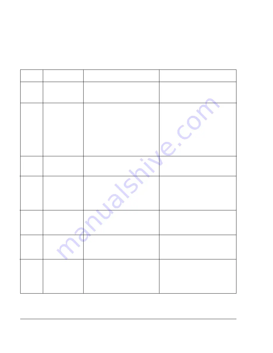
5.1. Identifying Alarm Codes and Recovering

GV3000/SE drive alarm codes are shown in table 5.1.  Note that the alarm code will
only be displayed for as long as the problem exists.  Once the problem has been
corrected, the alarm code will disappear from the display.

Table 5.1  -  List of Alarm Codes

Alarm

Description

Analog input signal
loss

High DC bus voltage

V/Hz identification
procedure active

V/Hz identification
procedure enabled

Low AC input line

Vector self-tuning
active

Vector self-tuning
enabled

Code

Aln

HIdc

I-Ac

I-En

LIL

S-Ac

S-En

Alarm Cause

P.011 = 8, 9, 10, or 11 and the 4 to
20 mA input is below 2 mA.

The DC bus is charged above the trip
threshold.  (DC bus is above 371 VDC.)

V/Hz identification procedure is
enabled and in progress.

H.020 = On; V/Hz identification
procedure has been enabled but
not started.

AC input line is low.

For SVC, indicates DC bus is being
regulated.  No corrective action is
required.

Vector self-tuning is enabled and in
progress.

U.008 = On; vector self-tuning has been
enabled but not started.

Summary of Contents for GV3000/SE 230

Page 1: ...Instruction Manual D2 3416 1 GV3000 SE 230 VAC 30 100 HP General Purpose Volts Hertz and Vector Duty Drive Software Start Up and Reference Manual Version 6 04 ...

Page 2: ... operate at and maintain zero speed The user is responsible for assuring safe conditions for operating personnel by providing suitable guards audible or visual alarms or other devices to indicate that the drive is operating or may operate at or near zero speed Failure to observe this precaution could result in severe bodily injury or loss of life ATTENTION Do not install modification kits with pow...

Page 3: ...P 028 3 5 3 5 The Keypad 3 6 3 6 Drive Status LEDs 3 8 Chapter 4 Programming Reference 4 1 Parameter Menus 4 1 4 2 Parameter Types 4 2 4 3 Displaying or Changing Parameter Values 4 3 4 4 Ensuring Program Security 4 5 4 5 First Menu Parameters 4 6 4 5 1 First Menu General Parameter Descriptions P 000 to P 006 4 6 4 6 Second Menu Parameters 4 11 4 6 1 Entering the Second Menu Password 4 11 4 6 2 Sec...

Page 4: ...eter Settings B 1 Appendix C Power Module Dependent Parameter Default Values 230 V Series C 1 Appendix D European and Japanese Default Parameter Settings D 1 Appendix E Configuring the Digital Inputs When the RMI Board is Installed in the Drive E 1 Appendix F Using the Terminal Strip Analog Input F 1 Appendix G Drive Regulation Overview G 1 ...

Page 5: ...Selection for Network Output Registers 4 54 Figure 4 10 Volts Hertz Ratio 4 57 Figure 4 11 Torque Boost Voltage 4 59 Figure 4 12 Avoidance Frequency Band 4 63 Figure 4 13 Volts Hertz Curve Selection 4 67 Figure 4 14 Motor Equivalent Circuit Diagram for Calculating Rotor Time Constant 4 82 Figure 4 15 Outer Control Loop Proportional Trim 4 92 Figure F 1 Terminal Strip Analog Input F 1 Figure F 2 An...

Page 6: ...nd P 008 Selection Combinations 4 18 Table 4 4 Preset Speed Digital Inputs 4 33 Table 4 5 Faults That Can Be Auto Reset 4 37 Table 4 6 AUTO MAN Key Status Based on P 000 and P 052 4 41 Table 4 7 STOP RESET Key Status Based on P 000 and P 055 4 46 Table 5 1 List of Alarm Codes 5 2 Table 5 2 List of Fault Codes 5 3 Table 5 3 Fatal Fault Codes That Can Be Reset 5 9 Table F 1 Analog Input Conversion S...

Page 7: ...egulation go to chapter 2 for the start up procedure For a description of all the parameters go to chapter 4 For troubleshooting guidelines go to chapter 5 For a description of the drive hardware refer to the GV3000 SE 230 VAC Drive Hardware Reference Installation and Troubleshooting instruction manual D2 3417 1 New Features in Version 6 04 The GV3000 SE version 6 04 software includes support for ...

Page 8: ...re describes how to program the minimum set of parameters that usually need to be programmed for applications using V Hz regulation Once you program these parameters their values are retained even if power is lost You only need to re program them if you want to change how the drive operates Your application may require programming other parameters in addition to the ones described in this start up...

Page 9: ... procedure Space is provided for recording information from three motors Motor rated amps Motor rated volts Motor base frequency Motor rated amps Motor rated volts Motor base frequency Motor rated amps Motor rated volts Motor base frequency Connect the drive to the motor Check that you have not been prevented from programming the drive If the PASSWORD LED on the keypad is on programming has been p...

Page 10: ...read section 1 1 for information you need to know before working with the drive Step 1 Power Up the Drive This step verifies that the drive powers up and passes the power up diagnostics After the drive passes the diagnostics the keypad display automatically enters monitor mode with speed displayed Turn power on AUTO MAN Forward Reverse PROGRAM RUN JOG STOP RESET START ENTER SPEED VOLTS AMPS Hz Kw ...

Page 11: ...eneral P parameters P 000 through P 005 P 000 selects where the drive is controlled from This procedure assumes local control from the keypad P 000 LOCL which is the default setting for the parameter Step 3 1 Press the ENTER key to display the first parameter P 000 Control Source AUTO MAN Forward Reverse PROGRAM RUN JOG STOP RESET START ENTER SPEED VOLTS AMPS Hz Kw TORQUE Password RUNNING REMOTE J...

Page 12: ...is 1 0 to 999 9 seconds VALUE ENTERED Step 3 5 Press the ENTER key to save the changed value AUTO MAN Forward Reverse PROGRAM RUN JOG STOP RESET START ENTER SPEED VOLTS AMPS Hz Kw TORQUE Password RUNNING REMOTE JOG AUTO FORWARD REVERSE PROGRAM After pressing ENTER the same parameter number is displayed You can now go to the next parameter Step 3 6 Press the key to display P 002 Decel Time 1 RAMP 1...

Page 13: ...eceleration time The adjustment range is 1 0 to 999 9 seconds VALUE ENTERED Step 3 9 Press the ENTER key to save the changed value AUTO MAN Forward Reverse PROGRAM RUN JOG STOP RESET START ENTER SPEED VOLTS AMPS Hz Kw TORQUE Password RUNNING REMOTE JOG AUTO FORWARD REVERSE PROGRAM After pressing ENTER the same parameter number is displayed You can now go to the next parameter Step 3 10 Press the k...

Page 14: ...word RUNNING REMOTE JOG AUTO FORWARD REVERSE PROGRAM After pressing ENTER the same parameter number is displayed You can now go to the next parameter AUTO MAN Forward Reverse PROGRAM RUN JOG STOP RESET START ENTER SPEED VOLTS AMPS Hz Kw TORQUE Password RUNNING REMOTE JOG AUTO FORWARD REVERSE PROGRAM Step 3 14 Press the key to display P 004 Maximum Speed AUTO MAN Forward Reverse PROGRAM RUN JOG STO...

Page 15: ... PROGRAM RUN JOG STOP RESET START ENTER SPEED VOLTS AMPS Hz Kw TORQUE Password RUNNING REMOTE JOG AUTO FORWARD REVERSE PROGRAM This shows that the default setting for Maximum Speed is 60 0 Hz Step 3 16 Press the key to increase maximum speed or the key to decrease maximum speed The adjustment range is 15 0 Hz to the value set for H 022 Overfrequency Limit The maximum value is 210 Hz VALUE ENTERED ...

Page 16: ...TORQUE Password RUNNING REMOTE JOG AUTO FORWARD REVERSE PROGRAM This parameter sets Current Limit which corresponds to the value in parameter P 095 Power Module Output Amps Step 3 19 Press the ENTER key to display the default setting of P 005 AUTO MAN Forward Reverse PROGRAM RUN JOG STOP RESET START ENTER SPEED VOLTS AMPS Hz Kw TORQUE Password RUNNING REMOTE JOG AUTO FORWARD REVERSE PROGRAM This s...

Page 17: ...econd Menu General P parameters and the Volts Hertz H parameters Step 4 1 Press the key to display parameter P 006 Second Menu Password This parameter allows you to enter the factory preset password that allows access to the Second Menu The Second Menu provides access to all parameters and the error log AUTO MAN Forward Reverse PROGRAM RUN JOG STOP RESET START ENTER SPEED VOLTS AMPS Hz Kw TORQUE P...

Page 18: ... RESET START ENTER SPEED VOLTS AMPS Hz Kw TORQUE Password RUNNING REMOTE JOG AUTO FORWARD REVERSE PROGRAM After pressing ENTER P 006 is displayed You now have access to all parameters and the error log After the password is entered the parameter value is reset to 0 Step 5 Program the Second Menu Volts Hertz H Parameters This step describes how to program the parameters that apply to V Hz regulatio...

Page 19: ...JOG AUTO FORWARD REVERSE PROGRAM Step 5 3 Press the ENTER key to access the first Volts Hertz parameter H 000 Motor Nameplate Volts This parameter sets the Motor Nameplate Volts and is taken directly from the motor nameplate AUTO MAN Forward Reverse PROGRAM RUN JOG STOP RESET START ENTER SPEED VOLTS AMPS Hz Kw TORQUE Password RUNNING REMOTE JOG AUTO FORWARD REVERSE PROGRAM Step 5 4 Press the ENTER...

Page 20: ...uency is not set correctly the monitor mode SPEED display will also not be scaled correctly AUTO MAN Forward Reverse PROGRAM RUN JOG STOP RESET START ENTER SPEED VOLTS AMPS Hz Kw TORQUE Password RUNNING REMOTE JOG AUTO FORWARD REVERSE PROGRAM This parameter adjusts the volts hertz ratio Base frequency is the set frequency at which the output voltage reaches the Motor Nameplate Voltage See figure 4...

Page 21: ...current or excess heating of the motor could result if this is not the case Failure to observe this precaution could result in damage to or destruction of the equipment This parameter specifies the Motor Nameplate Amps and is taken directly from the motor nameplate AUTO MAN Forward Reverse PROGRAM RUN JOG STOP RESET START ENTER SPEED VOLTS AMPS Hz Kw TORQUE Password RUNNING REMOTE JOG AUTO FORWARD...

Page 22: ...rd RUNNING REMOTE JOG AUTO FORWARD REVERSE PROGRAM Step 5 14 Press the key to display H 003 Torque Boost Voltage AUTO MAN Forward Reverse PROGRAM RUN JOG STOP RESET START ENTER SPEED VOLTS AMPS Hz Kw TORQUE Password RUNNING REMOTE JOG AUTO FORWARD REVERSE PROGRAM This parameter is required to offset the voltage drop of the motor at low speeds and produce constant torque For example high friction l...

Page 23: ...save the changed value After pressing ENTER the same parameter is displayed You can now move to the next parameter AUTO MAN Forward Reverse PROGRAM RUN JOG STOP RESET START ENTER SPEED VOLTS AMPS Hz Kw TORQUE Password RUNNING REMOTE JOG AUTO FORWARD REVERSE PROGRAM Step 5 18 Press the key until H 017 Input Power Snubber Configuration is displayed This parameter selects the input power supply type ...

Page 24: ...C input snubber resistor used ride through enabled 2 DC input snubber resistor not used ride through disabled 3 DC input snubber resistor used ride through disabled 4 DC input snubber resistor not used ride through enabled 5 DC input snubber resistor used ride through enabled VALUE ENTERED AUTO MAN Forward Reverse PROGRAM RUN JOG STOP RESET START ENTER SPEED VOLTS AMPS Hz Kw TORQUE Password RUNNIN...

Page 25: ... Forward Reverse PROGRAM RUN JOG STOP RESET START ENTER SPEED VOLTS AMPS Hz Kw TORQUE Password RUNNING REMOTE JOG AUTO FORWARD REVERSE PROGRAM Step 5 24 Press the key to increase the selection value to 1 or 2 or leave it at 0 The adjustment range is 0 Linear curve 1 Optimized curve for Reliance Electric RPM AC motors 2 For centrifugal pump and fan motor applications VALUE ENTERED Step 5 25 Press t...

Page 26: ...ward Reverse PROGRAM RUN JOG STOP RESET START ENTER SPEED VOLTS AMPS Hz Kw TORQUE Password RUNNING REMOTE JOG AUTO FORWARD REVERSE PROGRAM Step 6 2 Press the PROGRAM key twice to exit program mode The display returns to monitor mode with speed displayed The SPEED LED is on and the PROGRAM LED is off AUTO MAN Forward Reverse PROGRAM RUN JOG STOP RESET START ENTER SPEED VOLTS AMPS Hz Kw TORQUE Passw...

Page 27: ...e motor disconnected from the load Step 7 1 Press the PROGRAM key until the PROGRAM LED turns off The keypad display will enter monitor mode AUTO MAN Forward Reverse PROGRAM RUN JOG STOP RESET START ENTER SPEED VOLTS AMPS Hz Kw TORQUE Password RUNNING REMOTE JOG AUTO FORWARD REVERSE PROGRAM Step 7 2 Verify that the AUTO LED is off press the AUTO MAN key until the AUTO LED turns off This selects th...

Page 28: ...p 7 7 Verify that you have selected RUN and FORWARD Press the START key AUTO MAN Forward Reverse PROGRAM RUN JOG STOP RESET START ENTER SPEED VOLTS AMPS Hz Kw TORQUE Password RUNNING REMOTE JOG AUTO FORWARD REVERSE PROGRAM The drive is now running The keypad display is in monitor mode and the SPEED RUNNING and FORWARD LEDs are on The drive should be running at minimum speed The sample display show...

Page 29: ...r W Step 7 13 Turn power on and press the START key Repeat Step 7 8 Step 7 14 To make sure that the drive is not inadvertently started turn off and lock out or tag power to the drive Verify that the motor direction is appropriate for the required machine direction and then connect the motor to the load Step 8 Run the Drive This step describes how to adjust the speed reference from the keypad and r...

Page 30: ... Kw TORQUE Password RUNNING REMOTE JOG AUTO FORWARD REVERSE PROGRAM This increases the drive speed reference and the motor will rotate up to maximum speed The monitor mode LEDs turn off when the reference is changed The display now shows the drive speed Your speed display may be different Step 8 3 Press the ENTER key to move to the VOLTS display AUTO MAN Forward Reverse PROGRAM RUN JOG STOP RESET ...

Page 31: ...d in P 025 Stop Type End of V Hz Start Up Procedure This is the end of the basic V Hz start up procedure When the start up values are final Appendix B can be used to record final settings To configure remaining parameters according to the specific application refer to Chapter 4 Programming Reference If you have purchased the Control and Configuration Software CS3000 save your configuration to a pe...

Page 32: ...dure describes how to program the minimum set of parameters that usually need to be programmed for applications using vector regulation Once you program these parameters their values are retained even if power is lost You only need to re program them if you want to change how the drive operates Your application may require programming other parameters in addition to the ones described in this star...

Page 33: ...regardless of base RPM Standard NEMA motors are as follows 3600 RPM 2 poles 1800 RPM 4 poles 1200 RPM 6 poles 900 RPM 8 poles Consult your motor supplier if you are unsure of the motor design you are using If an encoder is used record the following encoder data Make sure the encoder is mounted to the motor and connected to the drive Encoder PPR Connect the drive to the motor and disconnect the mot...

Page 34: ... 1 for information you need to know before working with the drive Step 1 Power Up the Drive This step verifies that the drive powers up and passes the power up diagnostics After the drive passes the diagnostics the keypad display automatically enters monitor mode with speed displayed Turn power on AUTO MAN Forward Reverse PROGRAM RUN JOG STOP RESET START ENTER SPEED VOLTS AMPS Hz Kw TORQUE Passwor...

Page 35: ...rameter in the First Menu P 000 is displayed AUTO MAN Forward Reverse PROGRAM RUN JOG STOP RESET START ENTER SPEED VOLTS AMPS Hz Kw TORQUE Password RUNNING REMOTE JOG AUTO FORWARD REVERSE PROGRAM Step 3 Enter the Second Menu Password This step is required to access the Second Menu General P parameters and Vector U parameters Step 3 1 Press the key until P 006 Second Menu Password is displayed This...

Page 36: ...ess to the Second Menu will be retained if the drive loses and then regains power AUTO MAN Forward Reverse PROGRAM RUN JOG STOP RESET START ENTER SPEED VOLTS AMPS Hz Kw TORQUE Password RUNNING REMOTE JOG AUTO FORWARD REVERSE PROGRAM Step 3 4 Press the ENTER key to save the password number After pressing ENTER P 006 is displayed You now have access to all parameters and the error log AUTO MAN Forwa...

Page 37: ...will perform a diagnostic check After the diagnostics the drive enters monitor mode with speed displayed Step 4 1 Press the key until P 048 Volts Hertz or Vector Regulation is displayed AUTO MAN Forward Reverse PROGRAM RUN JOG STOP RESET START ENTER SPEED VOLTS AMPS Hz Kw TORQUE Password RUNNING REMOTE JOG AUTO FORWARD REVERSE PROGRAM Step 4 2 Press the ENTER key The default setting for P 048 is V...

Page 38: ...ote the display After the regulation selection is changed the drive will perform diagnostics and displays SELF with all monitor mode and status LEDs on When the diagnostics are complete the keypad display will enter monitor mode with speed displayed AUTO MAN Forward Reverse PROGRAM RUN JOG STOP RESET START ENTER SPEED VOLTS AMPS Hz Kw TORQUE Password RUNNING REMOTE JOG AUTO FORWARD REVERSE PROGRAM...

Page 39: ...AUTO MAN Forward Reverse PROGRAM RUN JOG STOP RESET START ENTER SPEED VOLTS AMPS Hz Kw TORQUE Password RUNNING REMOTE JOG AUTO FORWARD REVERSE PROGRAM Step 5 2 Press the ENTER key to display the first parameter P 000 Control Source The default setting for P 000 is LOCL or local control AUTO MAN Forward Reverse PROGRAM RUN JOG STOP RESET START ENTER SPEED VOLTS AMPS Hz Kw TORQUE Password RUNNING RE...

Page 40: ... 0 1 to 999 9 seconds VALUE ENTERED Step 5 6 Press the ENTER key to save the changed value After pressing ENTER the same parameter number is displayed You can now go to the next parameter AUTO MAN Forward Reverse PROGRAM RUN JOG STOP RESET START ENTER SPEED VOLTS AMPS Hz Kw TORQUE Password RUNNING REMOTE JOG AUTO FORWARD REVERSE PROGRAM Step 5 7 Press the key to display P 002 Decel Time 1 RAMP1 Th...

Page 41: ...d RUNNING REMOTE JOG AUTO FORWARD REVERSE PROGRAM Step 5 9 Press the key to increase deceleration time or the key to decrease deceleration time The adjustment range is 0 1 to 999 9 seconds VALUE ENTERED Step 5 10 Press the ENTER key to save the changed value After pressing ENTER the same parameter number is displayed You can now go to the next parameter AUTO MAN Forward Reverse PROGRAM RUN JOG STO...

Page 42: ... or loss of life This parameter sets the minimum speed in RPM AUTO MAN Forward Reverse PROGRAM RUN JOG STOP RESET START ENTER SPEED VOLTS AMPS Hz Kw TORQUE Password RUNNING REMOTE JOG AUTO FORWARD REVERSE PROGRAM Step 5 12 Press the ENTER key to display the default setting of P 003 This displays the default setting for Minimum Speed 150 RPM AUTO MAN Forward Reverse PROGRAM RUN JOG STOP RESET START...

Page 43: ... safe operation at the maximum operating speed of the drive For vector regulation overspeed detection in the drive determines when the drive shuts down and is factory set to 130 of maximum speed Failure to observe this precaution could result in bodily injury This parameter sets the maximum speed in RPM AUTO MAN Forward Reverse PROGRAM RUN JOG STOP RESET START ENTER SPEED VOLTS AMPS Hz Kw TORQUE P...

Page 44: ... AMPS Hz Kw TORQUE Password RUNNING REMOTE JOG AUTO FORWARD REVERSE PROGRAM Step 5 19 Press the key until P 005 Current Limit is displayed This parameter sets the stator current limit as a percentage of motor rated amps AUTO MAN Forward Reverse PROGRAM RUN JOG STOP RESET START ENTER SPEED VOLTS AMPS Hz Kw TORQUE Password RUNNING REMOTE JOG AUTO FORWARD REVERSE PROGRAM Step 5 20 Press the ENTER key...

Page 45: ...UTO MAN Forward Reverse PROGRAM RUN JOG STOP RESET START ENTER SPEED VOLTS AMPS Hz Kw TORQUE Password RUNNING REMOTE JOG AUTO FORWARD REVERSE PROGRAM Step 6 Program the Second Menu Vector U Parameters This step describes how to program the Vector U parameters that apply to vector regulation only You will not be adjusting any parameters for V Hz regulation H parameters in this procedure Step 6 1 Pr...

Page 46: ... 000 Torque Reference Source This parameter specifies the source for the torque reference The source can be the output of the speed loop the default the analog input the option port or the selected speed reference This procedure assumes that the torque reference is taken from the speed loop AUTO MAN Forward Reverse PROGRAM RUN JOG STOP RESET START ENTER SPEED VOLTS AMPS Hz Kw TORQUE Password RUNNI...

Page 47: ...6 7 Press the key to display U 001 Encoder PPR ATTENTION The Setting of parameters U 001 Encoder PPR U 002 Motor Poles U 003 Motor Nameplate Base Frequency U 005 Motor Nameplate RPM and U 017 Motor Top Speed determines the motor maximum speed These parameters must be set by a qualified person who understands the significance of setting them accurately Failure to observe this precaution could resul...

Page 48: ...AMPS Hz Kw TORQUE Password RUNNING REMOTE JOG AUTO FORWARD REVERSE PROGRAM Step 6 9 Press the key to increase the PPR or the key to decrease the PPR Select one of the four PPR values if an encoder is used Select SE if an encoder is not used See the description of U 001 in Chapter 4 for more information VALUE ENTERED Step 6 10 Press the ENTER key to save the changed value After pressing ENTER the s...

Page 49: ...er to Chapter 4 AUTO MAN Forward Reverse PROGRAM RUN JOG STOP RESET START ENTER SPEED VOLTS AMPS Hz Kw TORQUE Password RUNNING REMOTE JOG AUTO FORWARD REVERSE PROGRAM Step 6 12 Press the ENTER key to display the default setting of U 002 ATTENTION Do not use a 4096 PPR encoder with 2 pole motor Overspeed and motor damage can result Failure to observe this precaution could result in bodily injury Th...

Page 50: ... RPM and U 017 Motor Top Speed determines the motor maximum speed These parameters must be set by a qualified person who understands the significance of setting them accurately Failure to observe this precaution could result in bodily injury This parameter is the Motor Nameplate Base Frequency and is taken from the motor nameplate AUTO MAN Forward Reverse PROGRAM RUN JOG STOP RESET START ENTER SPE...

Page 51: ...NTER SPEED VOLTS AMPS Hz Kw TORQUE Password RUNNING REMOTE JOG AUTO FORWARD REVERSE PROGRAM Step 6 19 Press the key to display U 004 Motor Nameplate Amps ATTENTION This parameter setting must not exceed the rated amps found on the motor nameplate Overcurrent or excess heating of the motor could result if this is not the case Failure to observe this precaution could result in damage to or destructi...

Page 52: ...amps The minimum and maximum allowed adjustment range for this value depends on the Power Module HP rating VALUE ENTERED Step 6 22 Press the ENTER key to save the changed value After pressing ENTER the same parameter is displayed You can now move to the next parameter AUTO MAN Forward Reverse PROGRAM RUN JOG STOP RESET START ENTER SPEED VOLTS AMPS Hz Kw TORQUE Password RUNNING REMOTE JOG AUTO FORW...

Page 53: ...meplate AUTO MAN Forward Reverse PROGRAM RUN JOG STOP RESET START ENTER SPEED VOLTS AMPS Hz Kw TORQUE Password RUNNING REMOTE JOG AUTO FORWARD REVERSE PROGRAM Step 6 24 Press the ENTER key to display the default setting of U 005 This displays the Motor Nameplate RPM setting The default depends on the HP rating of the Power Module The display shown here is only an example Step 6 25 Press the key to...

Page 54: ...d result in damage to or destruction of the equipment This parameter is the percent of magnetizing current with respect to motor rated amps Note that when the vector regulation self tuning procedure is performed Step 8 the value of this parameter is automatically calculated You do not need to enter a value now AUTO MAN Forward Reverse PROGRAM RUN JOG STOP RESET START ENTER SPEED VOLTS AMPS Hz Kw T...

Page 55: ...d value After pressing ENTER the same parameter is displayed You can now move to the next parameter AUTO MAN Forward Reverse PROGRAM RUN JOG STOP RESET START ENTER SPEED VOLTS AMPS Hz Kw TORQUE Password RUNNING REMOTE JOG AUTO FORWARD REVERSE PROGRAM Step 6 32 Press the key to display U 022 Motor Nameplate Horsepower This parameter specifies the motor horsepower as it appears on the motor nameplat...

Page 56: ...e value if it is different from the motor nameplate The adjustment range is 0 3 to 600 0 HP VALUE ENTERED Step 6 35 Press the ENTER key to save the displayed value After pressing ENTER the same parameter is displayed You can now move to the next parameter AUTO MAN Forward Reverse PROGRAM RUN JOG STOP RESET START ENTER SPEED VOLTS AMPS Hz Kw TORQUE Password RUNNING REMOTE JOG AUTO FORWARD REVERSE P...

Page 57: ... PROGRAM Step 7 2 Press the ENTER key to display the default setting of U 017 This displays the default setting for the Motor Top Speed The actual setting depends on the Power Module HP type The display shown here is only an example AUTO MAN Forward Reverse PROGRAM RUN JOG STOP RESET START ENTER SPEED VOLTS AMPS Hz Kw TORQUE Password RUNNING REMOTE JOG AUTO FORWARD REVERSE PROGRAM Step 7 3 Check t...

Page 58: ...ucers belts and brakes Failure to observe this precaution could result in damage to or destruction of the equipment This step describes how to start the vector regulator self tuning procedure This procedure is enabled by setting parameter U 008 Torque Self Tune Enable to ON Self tuning is performed by the drive and determines the proper no load current value for parameter U 006 and for flux vector...

Page 59: ... key to display U 008 Torque Self Tune Enable Parameter U 008 is displayed AUTO MAN Forward Reverse PROGRAM RUN JOG STOP RESET START ENTER SPEED VOLTS AMPS Hz Kw TORQUE Password RUNNING REMOTE JOG AUTO FORWARD REVERSE PROGRAM Step 8 2 Press the ENTER key The default setting of OFF is displayed AUTO MAN Forward Reverse PROGRAM RUN JOG STOP RESET START ENTER SPEED VOLTS AMPS Hz Kw TORQUE Password RU...

Page 60: ...QUE Password RUNNING REMOTE JOG AUTO FORWARD REVERSE PROGRAM Step 8 6 Press the START key to begin the self tuning procedure ATTENTION The motor will rotate during the self tuning procedure Stay clear of rotating machinery Failure to observe this precaution could result in severe bodily injury or loss of life The display flashes S Ac indicating that the self tuning procedure is active This procedu...

Page 61: ... START ENTER SPEED VOLTS AMPS Hz Kw TORQUE Password RUNNING REMOTE JOG AUTO FORWARD REVERSE PROGRAM Step 9 Check Self Tuning Results The results of the self tuning procedure is displayed in U 009 This step describes how to view the results if SF is displayed after the test is started Step 9 1 Press the PROGRAM key until the PROGRAM LED turns on to enter program mode The display returns to the Vect...

Page 62: ...and lock out or tag power source if contact must be made Failure to observe this precaution could result in severe bodily injury or loss of life Important The stop input on the terminal strip is not active when the Control Source parameter P 000 is set to LOCL as it is during this start up procedure Use the STOP RESET key if you need to stop the drive Step 10 Check Motor Rotation Direction This st...

Page 63: ...If the speed reference is at minimum speed then proceed to Step 10 6 If the speed reference is not at minimum speed proceed to Step 10 5 Step 10 5 Press the key to decrease the speed reference value Step 10 6 Press the ENTER key to return to monitor mode AUTO MAN Forward Reverse PROGRAM RUN JOG STOP RESET START ENTER SPEED VOLTS AMPS Hz Kw TORQUE Password RUNNING REMOTE JOG AUTO FORWARD REVERSE PR...

Page 64: ...E JOG AUTO FORWARD REVERSE PROGRAM When the STOP RESET key is pressed the RUNNING LED turns off Step 10 10 Turn off and lock out or tag power to the drive Step 10 11 Verify that the DC bus capacitors are discharged Refer to hardware reference manual for this procedure Step 10 12 Switch any two of the motor leads U V or W and A and A NOT on the encoder Step 10 13 Turn power on and press the START k...

Page 65: ...PROGRAM Step 11 2 Press the or key once All monitor mode LEDs will turn off Increase the speed reference to the maximum value by using the key Wait five seconds or press the ENTER key to return to monitor mode This increases the drive speed reference and the motor will rotate up to maximum speed The monitor mode LEDs turn off when the reference is changed The display now shows the actual drive spe...

Page 66: ...ctual reading may be different VALUE READ AUTO MAN Forward Reverse PROGRAM RUN JOG STOP RESET START ENTER SPEED VOLTS AMPS Hz Kw TORQUE Password RUNNING REMOTE JOG AUTO FORWARD REVERSE PROGRAM Step 11 6 Press the STOP RESET key The driven motor should stop as programmed in P 025 Stop Type AUTO MAN Forward Reverse PROGRAM RUN JOG STOP RESET START ENTER SPEED VOLTS AMPS Hz Kw TORQUE Password RUNNING...

Page 67: ...or mode and the RUNNING and FORWARD LEDs are on Speed is displayed AUTO MAN Forward Reverse PROGRAM RUN JOG STOP RESET START ENTER SPEED VOLTS AMPS Hz Kw TORQUE Password RUNNING REMOTE JOG AUTO FORWARD REVERSE PROGRAM Sep 12 2 Press the PROGRAM key to enter program mode The PROGRAM LED is on and the First Menu General P parameter main menu is displayed AUTO MAN Forward Reverse PROGRAM RUN JOG STOP...

Page 68: ...y result in faster response but may result in less stability If the drive overshoots the speed reference when changes to the reference are made or if the drive is unstable reduce the value AUTO MAN Forward Reverse PROGRAM RUN JOG STOP RESET START ENTER SPEED VOLTS AMPS Hz Kw TORQUE Password RUNNING REMOTE JOG AUTO FORWARD REVERSE PROGRAM Step 12 7 Press the ENTER key when the value is acceptable S...

Page 69: ...to the functions listed above if the control source is local the REMOTE LED is off the keypad is also used to select run or jog select motor direction and start the drive Regardless of the control source selection the keypad display can be used to stop the drive reset drive faults and switch between a manual speed reference or the selected control source auto reference Important The STOP RESET key...

Page 70: ...cate the selected reference display Refer to section 3 1 1 Figure 3 2 Example of a Monitor Mode Display 3 1 1 Displaying the Selected Reference In monitor mode you can display the speed reference speed or frequency or the torque reference the drive is using while it is running RUNNING LED is on JOG LED is off Follow these steps to display the selected reference Step 1 If you are not already in mon...

Page 71: ...ual speed reference Note that the speed reference is in the units defined in P 028 Important The drive accepts the value as it is changed You do not have to press the ENTER key to save the value as you do with parameter entry Step 3 Press the ENTER key or wait approximately 5 seconds without pressing the or keys to return to monitor mode If the drive is not running you must press the ENTER key to ...

Page 72: ...tput values Figures 3 2 and 3 3 show sample displays 3 4 1 Display Range Normally a minus sign is used as one of the four characters in the display to indicate a negative value If a value including the minus sign exceeds four characters the display will drop the minus sign and display four digits In this case the SPEED LED will flash to indicate that the displayed value is a negative number Refer ...

Page 73: ...s This does not apply for the speed display For the speed display the FORWARD or REVERSE LEDs indicate actual speed reference polarity 3 4 2 Scaling the Manual Reference Speed Display and Reference Display Using P 028 In versions 5 0 and later the values displayed for the manual reference the output speed and the selected speed reference represent relative speed as opposed to always being displaye...

Page 74: ...r manual to auto the drive will ramp to the reference level provided by the new source at the rate specified in P 001 Accel Time 1 P 002 Decel Time 1 P 017 Accel Time 2 or P 018 Decel Time 2 Be aware that an abrupt speed change may occur depending upon the new reference level and the rate specified in these parameters Failure to observe this precaution could result in bodily injury If the control ...

Page 75: ...escriptions for more information Refer to the P 027 Forward Reverse Configuration parameter description for more information Use the PROGRAM key to move between program and monitor modes The PROGRAM LED turns on when the keypad display is in program mode and turns off when the keypad display is in monitor mode Use the RUN JOG key to toggle between run and jog when in local control REMOTE LED is of...

Page 76: ...reverse The keypad display is in program mode The keypad display is in monitor mode Parameters cannot be modified from the keypad without entering the correct password into P 051 Programming Disable See section 4 4 Ensuring Program Security for more information Note that disabling program changes by means of P 051 will not prevent parameter changes being made from the serial port or the network Pa...

Page 77: ...s value is scaled in parameter P 028 Drive output volts are displayed This value is not DC bus volts Drive output amps are displayed Drive output frequency in hertz is displayed Output power of the drive in kilowatts is displayed Note that this is intended for display purposes as a general indication of kilowatt output and should not be used for control or exact metering purpose Motor output torqu...

Page 78: ...rameters apply to both vector and V Hz applications Volts Hertz parameters H 000 through H 022 These parameters are used only for V Hz applications and are displayed if U H is selected in parameter P 048 Volts Hertz or Vector Regulation Vector parameters U 000 through U 048 These parameters are used only for vector applications and are displayed if UEC is selected in parameter P 048 Unless specifi...

Page 79: ...meter Types There are three types of parameters Configurable These parameters can be adjusted or changed only while the drive is stopped Tunable These parameters can be adjusted or changed while the drive is running or stopped Read only These parameters cannot be adjusted Each parameter is described in detail in this chapter The following information is provided for each parameter Parameter Number...

Page 80: ...or Changing Parameter Values Use the following procedure to display or change parameter values Step 1 Press the PROGRAM key until the PROGRAM LED turns on to enter program mode One of the main parameter menus P H U Err etc will be displayed AUTO MAN Forward Reverse PROGRAM RUN JOG STOP RESET START ENTER SPEED VOLTS AMPS Hz Kw TORQUE Password RUNNING REMOTE JOG AUTO FORWARD REVERSE PROGRAM Step 2 U...

Page 81: ...verse PROGRAM RUN JOG STOP RESET START ENTER SPEED VOLTS AMPS Hz Kw TORQUE Password RUNNING REMOTE JOG AUTO FORWARD REVERSE PROGRAM Step 5 Once the desired parameter is displayed press the ENTER key to access it The parameter value will be displayed AUTO MAN Forward Reverse PROGRAM RUN JOG STOP RESET START ENTER SPEED VOLTS AMPS Hz Kw TORQUE Password RUNNING REMOTE JOG AUTO FORWARD REVERSE PROGRAM...

Page 82: ...cted using parameter P 051 Programming Disable When programming is disabled parameter values can be displayed but cannot be modified from the keypad unless the correct password is entered in P 051 Note that disabling program changes by means of P 051 will not prevent parameter changes being made from the serial port on the network ATTENTION It is the user s responsibility to determine how to distr...

Page 83: ...ing LOCL Parameter Type Configurable Refer also to parameters P 007 Terminal Strip Digital Inputs Configure P 008 Terminal Strip Speed Reference Source P 063 Option Port Network Reference Source For more information about the Control and Configuration Software CS3000 refer to instruction manual D2 3348 For more information about the GV3000 SE OIM Operator Interface Module M N 2RK3000 refer to inst...

Page 84: ...ct the DeviceNetTM Network option board the AutoMaxTM Network option board the PROFIBUS or the ControlNetTM Network option board as the drive control source Note that the REMOTE LED will turn on if any control source other than the local keypad is selected P 001 Accel Time 1 RAMP 1 For V Hz regulation this parameter specifies the amount of time in which the motor ramps from zero speed to Maximum S...

Page 85: ... Current Limit U 017 Motor Top Speed U 024 High DC Bus Fault Avoidance Enable The time the motor takes to make any speed decrease except a coast to rest stop is directly proportional to the value in this parameter This parameter does not apply if JOG is selected See P 022 Jog Ramp Decel Time Note that motor load inertia and input line conditions can extend the deceleration time to a value greater ...

Page 86: ...d reference is supplied the regulation will not command a speed greater than the value in P 004 Parameter Range 15 0 to H 022 Overfrequency Limit V Hz 10 RPM to U 017 Motor Top Speed vector Default Setting 60 0 Hz V Hz 1722 RPM vector Parameter Type Tunable Refer also to parameters P 028 RPM Display Scaling H 022 Overfrequency Limit U 017 Motor Top Speed ATTENTION The user is responsible for ensur...

Page 87: ...educes output current For vector regulation Current limit is a percentage of the value entered in U 004 The output current will be limited to the current limit value which may result in motor speed decreasing or the acceleration deceleration time being extended P 006 Second Menu Password This parameter is used to enable disable access to Second Menu General P Vector U Volts Hertz H and RMI r param...

Page 88: ...ing the Second Menu Password ATTENTION It is the user s responsibility to determine how to distribute the second menu password Reliance Electric is not responsible for unauthorized access violations within the user s organization Failure to observe this precaution could result in bodily injury The Second Menu Password parameter P 006 is used to enable disable access to the Second Menu parameters W...

Page 89: ...r is accessed AUTO MAN Forward Reverse PROGRAM RUN JOG STOP RESET START ENTER SPEED VOLTS AMPS Hz Kw TORQUE Password RUNNING REMOTE JOG AUTO FORWARD REVERSE PROGRAM AUTO MAN Forward Reverse PROGRAM RUN JOG STOP RESET START ENTER SPEED VOLTS AMPS Hz Kw TORQUE Password RUNNING REMOTE JOG AUTO FORWARD REVERSE PROGRAM Step 4 Press the ENTER key to access the parameter AUTO MAN Forward Reverse PROGRAM ...

Page 90: ...D VOLTS AMPS Hz Kw TORQUE Password RUNNING REMOTE JOG AUTO FORWARD REVERSE PROGRAM AUTO MAN Forward Reverse PROGRAM RUN JOG STOP RESET START ENTER SPEED VOLTS AMPS Hz Kw TORQUE Password RUNNING REMOTE JOG AUTO FORWARD REVERSE PROGRAM Access Disabled AUTO MAN Forward Reverse PROGRAM RUN JOG STOP RESET START ENTER SPEED VOLTS AMPS Hz Kw TORQUE Password RUNNING REMOTE JOG AUTO FORWARD REVERSE PROGRAM...

Page 91: ...e from the terminal strip will cause power to be applied to the motor if the remote start contact is closed Stay clear of rotating machinery in this case Failure to observe this precaution could result in bodily injury An unasserted open or asserted closed input will select the input functions as shown in table 4 2 If a function is not configured the unasserted open state will be applied Table 4 2...

Page 92: ... Note that if an OIM is connected REM LOC will switch control from the terminal strip to the OIM not to the local keypad The digital input for REM LOC is active only if the control source is remote The following example shows how this input can be used REM LOC Input Example Assume the drive is stopped and started using an external two wire control signal The drive s control source is the terminal ...

Page 93: ...peed the speed regulator is preset with the last torque reference When switching from speed to torque the torque regulator will switch to the new torque reference The digital input for TRQ SPD is active if the control source is local remote or serial Inrteraction with P 008 The default value of 0 for P 007 will limit P 008 Terminal Strip Speed Reference Source to a selection of 0 You must change P...

Page 94: ...ll terminal strip digital inputs 5 Analog reference and one 1 preset speed Uses terminal strip digital input 6 Digital inputs 7 and 8 are not used 6 Analog reference and three 3 preset speeds Uses terminal strip digital inputs 6 and 7 Digital input 8 is not used 7 Analog reference and seven 7 preset speeds Uses terminal strip digital inputs 6 7 and 8 Default Setting 0 Parameter Type Configurable R...

Page 95: ...input a value of 1 equals an offset of approximately 10 mV For 0 to 20 mA input a value of 1 equals an offset of approximately 20 µA For more information about the analog input refer to Appendix F Selection combination is acceptable P 007 P 008 Selection Example If you want to select the MOP as the speed reference source P 008 must be set to 1 Next select the value for P 007 using table 4 3 Follow...

Page 96: ...1 P 031 as reference on signal loss 11 4 to 20 mA inverted Display alarm and use Preset Speed 1 P 031 as reference on signal loss Default Setting 2 Parameter Type Tunable Refer also to parameters P 009 Terminal Strip Analog Input Offset P 010 Terminal Strip Analog Input Gain P 010 Terminal Strip Analog Input Gain This parameter is used to compensate for component tolerance errors or insufficient v...

Page 97: ...set by 4 mA offset parameter P 009 low limited at 0 multiplied by P 010 and then negated If P 011 6 the input offset P 009 will be low limited at 0 and multiplied by P 010 If P 011 7 the input offset P 009 will be low limited at 0 multiplied by P 010 and then negated For the 4 to 20 mA input selections the drive can be configured to generate a fault selections 4 and 5 or an alarm selections 8 thro...

Page 98: ...cation is active 4 Output relay is energed when all start permissive conditions are met 5 Output relay is energed when one or more alarms are active Default Setting 0 Parameter Type Configurable Refer also to parameters N A For example for an application using an output contactor you can obtain a 0 5 second delay between a start assertion and the generation of motor voltage by setting P 013 to 1 T...

Page 99: ... board analog input 6 RMI board frequency input 7 Switched RMI board analog input or frequency input 8 RMI outer loop PI block Mode 1 9 RMI outer loop PI block Mode 2 Default Setting 0 Parameter Type Configurable Refer also to parameters P 015 Trim Gain Percentage Selections 5 through 9 are available only if an optional RMI board is installed in the drive Refer to instruction manual D2 3341 for mo...

Page 100: ... Selected Speed Ref To Speed Ref Limit Block 100 100 Selected Trim Ref P 014 Figure 4 4 Draw and Trim Gain See Appendix G for the complete block diagram P 016 Draw Gain Percentage This parameter is used to increase or decrease the selected speed reference to the speed regulator Parameter Range 99 9 to 99 9 1 0 1 Default Setting 0 0 Parameter Type Tunable Refer also to parameters N A This parameter...

Page 101: ...ncrease is directly proportional to the value in this parameter This parameter does not apply if JOG is selected P 018 Decel Time 2 RAMP 2 This parameter specifies the deceleration time when a second ramp selection is configured as a digital input When the RAMP 2 deceleration time digital input is asserted the RAMP 2 acceleration time also takes effect In V Hz regulation this parameter specifies t...

Page 102: ...ble Refer also to parameters P 001 Accel Time 1 P 002 Decel Time 1 P 017 Accel Time 2 P 018 Decel Time 2 Important This parameter does not apply to the Jog Ramp Accel Time P 021 or Jog Ramp Decel Time P 022 parameters The acceleration and deceleration times must be set the same for the S Curve ramp to function the same for acceleration as for deceleration If the deceleration time is set lower than...

Page 103: ...inimum Speed P 004 Maximum Speed P 021 Jog Ramp Accel Time For V Hz regulation this parameter specifies the amount of time seconds it takes the motor to ramp from zero speed to Maximum Speed P 004 when JOG is selected For vector regulation this parameter specifies the amount of time seconds it takes the motor to ramp from zero speed to Motor Top Speed U 017 when JOG is selected Parameter Range 1 0...

Page 104: ...ed P 022 Jog Ramp Decel Time For V Hz regulation this parameter specifies the amount of time it takes the motor to ramp from Maximum Speed P 004 to zero speed when JOG is selected For vector regulation this parameter specifies the amount of time it takes the motor to ramp from Motor Top Speed U 017 to zero speed when JOG is selected The time the motor takes to make any speed decrease except a coas...

Page 105: ...08 Terminal Strip Speed Reference Source the last value in effect prior to the MOP being disabled will be retained P 025 Stop Type This parameter selects how the motor will stop when a stop command is given Parameter Range 0 Coast to rest stop 1 Ramp stop Default Setting 0 Parameter Type Tunable Refer also to parameters P 002 Decel Time 1 P 018 Decel Time 2 P 022 Jog Ramp Decel Time U 000 Torque R...

Page 106: ...e of P 025 If P 025 0 pressing the STOP RESET key or giving an external stop command will cause the motor to coast to rest If P 025 1 pressing the STOP RESET key or giving an external stop command will cause the motor to ramp to rest within a time equal to or greater than the preset deceleration time P 022 Note that when the START input from the selected control source is released unasserted the m...

Page 107: ... regardless of the polarity of the speed reference input When P 027 is set to 2 the state of the forward reverse input is latched when the motor is started RUNNING LED is on Direction changes requested from any control source after the motor is started are ignored Note however that this selection will not inhibit a motor direction change due to a change in the polarity of the speed reference input...

Page 108: ... the maximum speed or the output speed as 800 gallons minute when operating at maximum speed H 001 Motor Nameplate Base Frequency 60 Step 1 Set parameter P 028 800 Step 2 Enter SPEED monitor mode by pressing the PROGRAM key until the PROGRAM LED turns off and the SPEED LED turns on Step 3 Start the drive press the START key Step 4 When the drive is running at half of rated speed the display shows ...

Page 109: ...tting N A Parameter Type Read only Refer also to parameters P 030 Elapsed Time Meter Reset P 030 Elapsed Time Meter Reset This parameter sets parameter P 029 Elapsed Time Meter and the error log clock to zero This parameter is set to OFF after the reset operation is carried out Parameter Range OFF No action ON Reset the Elapsed Time Meter P 029 and the error log clock to zero 0 Default Setting OFF...

Page 110: ...2 3341 for more information Table 4 4 Preset Speed Digital Inputs Digital Inputs Terminals 7 18 0 open 0 open 1 closed 1 closed 0 open 0 open 1 closed 1 closed 6 19 0 open 1 closed 0 open 1 closed 0 open 1 closed 0 open 1 closed 8 17 0 open 0 open 0 open 0 open 1 closed 1 closed 1 closed 1 closed Selected Speed Reference P 031 or analog input see P 008 selections 5 6 and 7 P 032 P 033 P 034 P 035 ...

Page 111: ...iagnostic This diagnostic is available for flux vector control FVC only Parameter Range OFF Disable encoder loss diagnostic ON Enable encoder loss diagnostic Default Setting OFF Parameter Type Tunable Refer also to parameters N A The encoder loss detection diagnostic is functional only when the drive is operating as a speed regulator not as a torque regulator When the diagnostic is enabled and fee...

Page 112: ...ermal overload relay is similar to a motor overload relay neither measures actual motor temperature Temperature measuring devices integral to the motor are the best way to thermally protect AC motors under all conditions P 040 Motor Overload Enable This parameter enables the electronic motor thermal overload function This function operates similarly to a motor overload relay to protect the motor f...

Page 113: ... on the display during a line dip ride through The levels for LIL and LU depend on the parameter setting for AC Line Voltage H 021 P 043 Fault Auto Reset Attempts This parameter selects the number of times the drive will attempt to reset drive faults Parameter Range 0 to 10 Default Setting 0 Parameter Type Configurable Refer also to parameters P 044 Fault Auto Reset Time Important The drive will r...

Page 114: ...lts cannot be auto reset Note that the auto reset feature will be disabled during the vector tuning operation and the V Hz identification procedure P 044 Fault Auto Reset Time This parameter specifies the amount of time the drive will wait to attempt to reset drive faults Parameter Range 1 to 60 seconds Default Setting 8 Parameter Type Configurable Refer also to parameters P 043 Fault Auto Reset A...

Page 115: ...ve fault is logged OPL is displayed The output phase loss diagnostic can be disabled to avoid nuisance faults which may occur for example when a small motor is used with a large Power Module P 047 Carrier Frequency kHz This parameter selects the drive s carrier frequency Parameter Range 2 2 kHz Carrier frequency 4 4 kHz Carrier frequency 8 8 kHz Carrier frequency Default Setting 4 Parameter Type C...

Page 116: ...ogram the drive for SVC by first selecting UEC in parameter P 048 and then selecting SE in parameter U 001 Encoder PPR Switching from one regulator type to the other V Hz to vector or vice versa takes approximately 5 seconds The drive will reinitiate power up diagnostics SELF appears on the display and all LEDs turn on for approximately 4 seconds Changing this parameter will also restore default v...

Page 117: ...ter values cannot be modified from the keypad unless the correct password is entered again Refer to section 4 4 Ensuring Program Security for more information Parameter Range 0 to 9999 Default Setting 0 Programming enabled Parameter Type Tunable Refer also to parameters N A ATTENTION It is the user s responsibility to determine how to distribute the password Reliance Electric is not responsible fo...

Page 118: ... used to protect against inadvertent reference change when the drive is controlled from the terminal strip P 000 rE or the option port P 000 OP Table 4 6 details whether the AUTO MAN key is active based on the selected control source and P 052 Note that this parameter is new in the release Table 4 6 AUTO MAN Key Status Based on P 000 and P 052 Control Source P 000 Front panel LOCL Terminal strip r...

Page 119: ...is a negative value a direction change will occur when the transition is made from AUTO to MANUAL Verify that the auto reference is a positive value and the FORWARD REVERSE command is appropriate to the application before making the transition from AUTO to MANUAL Important If the manual reference is being modified using the front panel keypad display when the transition from AUTO to MANUAL is made...

Page 120: ...g the function loss input immediately starts the drive without any change to the start or stop input When this function is enabled the user must ensure that automatic start up of the driven equipment will not cause injury to operating personnel or damage to the driven equipment In addition the user is responsible for providing suitable audible or visual alarms or other devices to indicate that thi...

Page 121: ...ced edge requirements do not apply if the control source is changed to any other value and then back again as shown in the following example Example Assume the selected control source is the terminal strip P 000 rE level sense start is enabled P 054 ON no faults are active and both the start and stop inputs are closed The drive therefore is running The drive is stopped using the front panel STOP k...

Page 122: ...other applicable equipment to alert personnel that the application uses an automatic start up feature Figure 4 8 shows an example of a typical circuit that can be used on 30 to 100 HP drives This circuit will energize an alarm device prior to motor start up Note that if P 000 rE the terminal strip LOC REM switch determines the control source local or remote at power up Figure 4 8 Sample Alarm Circ...

Page 123: ...he drive in an easily accessible location As a further safety precaution the user should post a warning on the drive to alert personnel that the STOP RESET key is not functional Failure to observe this precaution could result in severe bodily injury or loss of life Table 4 7 details whether the STOP RESET key is active based on the selected control source P 000 and P 055 Table 4 7 STOP RESET Key S...

Page 124: ...cation Option Board manual HE HGV3DN For ControlNet applications refer to the ControlNet Network Communication Option Board manual D2 3390 Setting P 061 0 provides basic drive control from the AutoMax network Only essential drive data reference sequencing basic tuning and feedback data are transferred over the network This allows a higher density network with moderate functionality Select the basi...

Page 125: ...oard manual HE HGV3DN For ControlNet applications refer to the ControlNet Network Communication Option Board manual D2 3390 If the option port is not in control of the drive but is only monitoring drive operation then loss of network communications will have no effect on drive operation In all cases the AutoMax Network Communications Option Board upon loss of communication with the network master ...

Page 126: ...TTENTION In vector regulation if U 000 Torque Reference Source is set to 2 Option Port and P 062 is set to 1 Hold Last Reference and the drive loses communication with the network the drive will no longer be regulating speed Instead motor speed will vary according to the load up to the overspeed limit Ensure that driven machinery all drive train mechanisms and application material are capable of s...

Page 127: ... the drive is running the terminal strip stop input will function as a STOP RUN input If the terminal strip stop input is opened the drive will stop If the terminal strip stop input is closed the drive will re start Failure to observe this precaution could result in severe bodily injury or loss of life Note that in this configuration it may not always be possible to stop the drive over the network...

Page 128: ...from register 33 of the drive s Drop_1 register map In V Hz regulation the value in register 33 represents speed in hertz scaled 0 to 4095 for 0 to Maximum Speed P 004 In vector regulation if U 000 2 the value in register 33 represents torque scaled 0 to 4095 for 0 to 150 torque If U 000 2 this value represents speed in RPM scaled 0 to 4095 for 0 to Top Speed U 017 Refer to the AutoMax Network Com...

Page 129: ...ference register 1 to 8 Broadcast register 1 to 8 respectively Default Setting 0 Parameter Type Configurable Refer also to parameters P 063 Option Port Network Reference Source U 000 Torque Reference Source The option port trim reference is used as the outer control loop reference and or the speed trim reference see the P 014 Trim Reference Source parameter description If P 064 0 the trim referenc...

Page 130: ...mpounding 3 Speed loop feedback 4 Speed loop error 5 Speed PI output 6 Outer control loop feedback 7 Outer control loop error 8 Outer control loop output 9 Terminal strip analog input normalized to speed see Appendix F 10 Terminal strip analog input scaled see Appendix F 11 Torque reference 12 Torque feedback Default Setting 0 Parameter Type Tunable Refer also to parameters N A These signals are v...

Page 131: ...gister 4 Source continued P 066 P 067 P 068 P 069 0 Motor KW display value 12 0 Encoder counter x 4 12 0 Output power factor 12 0 Motor torque display value 12 Network Output Register 1 Network Output Register 2 Network Output Register 3 Network Output Register 4 Network Module Figure 4 9 Signal Selection for Network Output Registers ...

Page 132: ...f messages received from the network 15 Network interface number of message receive time out errors 16 Network interface number of message CRC errors 17 Network interface number of message overrun errors 18 Network interface number of messages aborted 19 Network interface number of messages transmitted to the network Default Setting 0 Parameter Type Tunable Refer also to parameters P 091 Diagnosti...

Page 133: ...acter Display P 090 1 terminal strip digital inputs 4 3 2 1 P 090 2 terminal strip digital inputs 8 7 6 5 P 090 4 RMI digital inputs 4 3 2 1 P 098 Software Version Number The parameter displays the software version number Parameter Range N A Default Setting N A Parameter Type Read only Refer also to parameters N A P 099 Power Module Type This parameter displays the type of Power Module the drive i...

Page 134: ...able Refer also to parameters H 003 Torque Boost Voltage H 018 Volts Hertz Curve Type Base frequency is the frequency at which th e output voltage reaches Motor Nameplate Voltage H 000 Below base frequency the output voltage varies with output frequency according to the V Hz adjustment in parameter H 018 Volts Hertz Curve Type Above base frequency output voltage is held constant as frequency incre...

Page 135: ...Motor Nameplate Volts H 000 Parameter Range 0 0 to 20 0 of nominal inverter voltage Default Setting 0 5 Parameter Type Configurable Refer also to parameters H 000 Motor Nameplate Volts Important If you set H 003 0 you must perform the identification test using H 020 prior to running Torque boost is required to offset the voltage drop of the AC motor at low speeds For high friction loads and high i...

Page 136: ...ad changes the long term speed behavior of the motor is greatly improved through the use of this parameter To calculate the value entered for H 004 use the following equation Synchronous RPM Nameplate RPM Max Power Module Amps Synchronous RPM Motor Nominal Current H 003 Torque Boost Voltage continued 100 Voltage Output Output Frequency Hz 1 0 Torque Boost H 003 1 Constant V Hz Ratio Base Frequency...

Page 137: ...OFF Parameter Type Tunable Refer also to parameters P 025 Stop Type H 006 DC Braking Start Frequency H 007 DC Braking Current H 008 DC Braking Time H 017 Input Power Snubber Configuration Important This function will not provide holding torque as a mechanical brake DC braking is only operative when Stop Type P 025 is set to 1 ramp stop DC braking is used to provide additional motor braking by DC c...

Page 138: ...DC Braking Enable H 007 DC Braking Current H 008 DC Braking Time H 007 DC Braking Current This parameter sets the DC current level applied to the motor during DC braking With DC braking enabled H 005 ON the braking torque provided by the motor is defined by a percentage of motor rated amps 100 is motor rated amps Important If H 007 is set too high faults may occur OC OCA OCb or PUo will be display...

Page 139: ...nce Frequency Enable This parameter enables the avoidance frequency bands selected in H 011 H 013 and H 015 Parameter Range OFF Disable avoidance frequency processing ON Enable avoidance frequency processing Default Setting OFF Parameter Type Tunable Refer also to parameters P 003 Minimum Speed P 004 Maximum Speed H 010 to H 015 Avoidance Frequency Midpoint and Band 1 2 and 3 Operating a motor con...

Page 140: ...1 2 and 3 This parameter specifies the midpoint of each avoidance frequency band selected in H 011 H 013 and H 015 The adjusted values may be in any order The frequency will not be affected at normal acceleration or deceleration but will be avoided at continuous output frequency Parameter Range 0 0 to 200 0 Hz Default Setting 0 0 Parameter Type Tunable Refer also to parameters H 009 Avoidance Freq...

Page 141: ...on in which the drive will search in order to synchronize to motor speed Parameter Range Off Disable synchronization F Search starts in motor forward direction r Search starts in motor reverse direction Fr Search starts in motor forward then reverse direction rF Search starts in motor reverse then forward direction Default Setting Off Parameter Type Configurable Refer also to parameters N A Note t...

Page 142: ... phase 50 60Hz or 380 460V 3 phase 50 60Hz set H 017 0 or 1 For DC input Power Modules set H 017 2 or 3 if multiple motors are connected to the inverter Set H 017 4 or 5 if a single motor is connected to the inverter Snubber Resistor If a snubber resistor is not used set H 017 0 2 or 4 If the DC bus voltage rises above a certain threshold 14 above the rectified nominal AC line the drive will incre...

Page 143: ... bus voltage drops below the low DC bus voltage threshold or the AC line drops out a low bus voltage fault LU will be generated and the drive will stop Refer to P 042 for more information regarding line dip ride through H 018 Volts Hertz Curve Type This parameter provides an application dependent selection of nominal motor voltage versus frequency This selection is effective from any control sourc...

Page 144: ...w to determine the cause of the fault Remove the cause and repeat the procedure 2 A function loss aborted the identification procedure Depending on Function Loss Response P 026 this is or is not logged Remove the cause and repeat the procedure 3 A stop command aborted the identification procedure Repeat the procedure without stopping 4 The identification procedure aborted because the measured curr...

Page 145: ...in the reverse direction even if reverse disable has been selected in P 027 Uncouple the motor from any driven machinery that could be damaged by reverse rotation Failure to observe this precaution could result in damage to or destruction of the equipment Before starting this procedure verify that the motor is at rest and connected to the drive The motor can be connected to the driven machinery Ve...

Page 146: ...etting 230 Parameter Type Configurable Refer also to parameters N A This parameter is the phase to phase line voltage provided to the drive input power terminals The value entered should be within 10 of actual line voltage If this parameter is set too low it may cause a drive fault on overvoltage H 022 Overfrequency Limit ATTENTION The user is responsible for ensuring that driven machinery all dri...

Page 147: ... input see the P 007 configuration or the network option board depending on the control source If torque regulation is selected the Current Limit parameter P 005 is not applied asserting the START input when JOG is selected will enable the torque regulator not the speed regulator i e P 020 P 021 and P 022 are not used the stop type will always be coast to rest regardless of the value in P 025 Stop...

Page 148: ...ed person who understands the significance of setting them accurately Failure to observe this precaution could result in bodily injury ATTENTION Do not use a 4096 PPR encoder with a 2 pole motor Overspeed and motor damage can result Failure to observe this precaution could result in bodily injury If an encoder is used select the PPR based on a 125 kHz maximum input frequency limitation The encoder...

Page 149: ...sing data on the motor nameplate as follows Step 1 Calculated the RPM value at 60 Hz as follows 60 Motor Nameplate Base Freq Hz U 003 Step 2 Determine the number of motor poles by looking up the value computed for RPM 60 Hz Range of RPM 60 Hz Number of Poles 3240 to 3600 2 1620 to 1800 4 1080 to 1200 6 810 to 900 8 If you change this parameter after performing self tuning using parameter U 008 you...

Page 150: ... Parameter Range 15 0 to 240 0 Hz Default Setting 60 0 Parameter Type Configurable Refer also to parameters U 002 Motor Poles U 005 Motor Nameplate RPM U 004 Motor Nameplate Amps This parameter identifies the motor rated amps as it appears on the motor nameplate ATTENTION This parameter must not exceed the rated amps found on the motor nameplate Overcurrent or excess heating of the motor could res...

Page 151: ...le dependent see Appendix C Parameter Type Configurable Refer also to parameters U 002 Motor Poles U 003 Motor Nameplate Base Frequency U 008 Torque Self Tune Enable The actual adjustment range changes based on the values in U 002 Motor Poles and U 003 Motor Nameplate Base Frequency In general the value range for U 005 is U 003 x 120 x 900 to U 003 x 120 x 999 U 002 U 002 If the value is too close...

Page 152: ... If this data does not appear on the motor nameplate perform the self tuning procedure U 008 to automatically calculate the result No Load Amps Motor Rated Amps Parameter Range 10 00 to 80 00 Default Setting Power Module dependent see Appendix C Parameter Type Configurable Refer also to parameters U 008 Torque Self Tune Enable U 007 Motor Nameplate Volts This parameter identifies motor rated volta...

Page 153: ...etermining the encoder PPR may be necessary since the PPR is not always listed on the motor or encoder nameplate Determining the magnetizing current ratio is necessary in vector regulation so that the proper no load current or magnetizing current is set The proper magnetizing current is required to develop rated motor torque speed and horsepower in vector regulation For FVC and SVC operation this ...

Page 154: ... to 80 of rated current Check to see that nothing is connected to the shaft and check the value in U 004 6 Bus voltage error Bus voltage out of range Check that the AC input line is 10 of U 018 7 Current limit exceeded Self tuning should be run with the motor unloaded and without being connected to any inertia load Default Setting N A Parameter Type Read only Refer also to parameters U 001 Encoder...

Page 155: ...changes to the reference are made or if the drive is unstable reduce the value With the default value the drive should perform satisfactorily However with increased inertia loads this parameter may need to be adjusted U 014 Torque Regulator Proportional Gain This parameter determines the performance of the torque response For most applications it is recommended that this value not be changed The h...

Page 156: ...s parameter sets the speed at which field weakening begins Parameter Range to U 005 Default Setting Power Module dependent see Appendix C Parameter Type Configurable Refer also to parameters U 002 Motor Poles U 003 Motor Nameplate Base Frequency U 005 Motor Nameplate RPM U 017 Motor Top Speed The low limit is calcilated as 80 of synchronous speed where Synch Speed Using a 60 Hz motor as an example...

Page 157: ...compares the results of two formulas and uses the lower value For FVC operation U 001 SE 4 x sync speed or 240 x For SVC operation U 001 SE 2 x sync speed or 240 x where sync speed 120 x Note that the drive limits the output frequency to the motor to 240 Hz Note the following about U 017 Increasing this number above Motor Nameplate RPM U 005 will increase the field weakening range The range of the...

Page 158: ...zing current regulator For most applications it is recommended that this parameter not be changed Parameter Range 0 10 to 31 99 Default Setting 0 15 Parameter Type Tunable Refer also to parameters U 020 Flux Current Regulator Integral Gain U 020 Flux Current Regulator Integral Gain This parameter determines the performance of the magnetizing current regulator For most applications it is recommende...

Page 159: ...ta as shown in figure 4 14 Parameter Range 100 to 9999 milliseconds Default Setting 250 Parameter Type Tunable Refer also to parameters N A Figure 4 14 Motor Equivalent Circuit Diagram for Calculating Rotor Time Constant To calculate the rotor time constant use the following formula Rotor time constant L R2 Where L Lm L2 Lm Xm 2 x 3 14 x 60 L2 X2 2 x 3 14 x 60 Note that this parameter is not funct...

Page 160: ...ble if the drive is configured as a torque regulator Parameter Range OFF Drive will not regulate the DC bus on a line dip condition ON Drive will decelerate the motor to attempt to hold up the DC bus on a line dip condition Default Setting OFF Parameter Type Tunable Refer also to parameters N A If this feature is enabled and DC bus voltage drops below 80 of normal the drive decelerates the motor e...

Page 161: ... an attempt to decrease the DC bus voltage level Note that this parameter is new in this release U 025 Zero Speed Hold Time This parameter selects the amount of time for which zero speed is held at the end of ramp stop sequence Parameter Range 0 0 to 20 0 seconds Default Setting 0 0 Parameter Type Tunable Refer also to parameters N A ATTENTION The motor is energized when the drive is operating at ...

Page 162: ...ameter Type Tunable Refer also to parameters U 026 Current Compounding Gain U 028 Losses Compensation Gain The inertia compensation signal can be either the S Ramp ramp block rate output dv dt used for standalone applications or a value provided directly from the network option Signal selection is controlled by a network register No corresponding parameter local to the drive is provided Inertia co...

Page 163: ...ed loop output and the inertia compensation signal to produce the final torque reference Refer to the speed loop block diagram in Appendix G U 030 SVC Slip Adjust Parameter Range 0 50 to 1 50 Default Setting 1 00 Parameter Type Tunable Refer also to parameters N A For SVC operation in the absence of a speed feedback device operation of the speed loop is based on an estimated speed feedback Estimat...

Page 164: ...rating in the desired direction even if reverse has been disabled in P 027 Stay clear of rotating machinery Failure to observe this precaution could result in bodily injury Note that when Forward Reverse Configuration P 027 is set to 1 setting this parameter to r Fr or rF may still cause the motor to operate in the reverse direction U 032 SVC Flux Current Regulator Gain This parameter specifies th...

Page 165: ...log input scaled see Appendix F 1 Speed loop PI output torque reference 4095 150 torque Default Setting 0 Parameter Type Configurable Refer also to parameters U 041 Outer Control Loop Lead Lag Select U 042 Outer Control Loop Lead Lag Low Frequency U 043 Outer Control Loop Lead Lag Ratio U 044 Outer Control Loop Reference Gain U 045 Outer Control Loop Proportional Gain U 046 Outer Control Loop Inte...

Page 166: ...may be restricted by the lead lag ratio setting U 043 See Appendix G for the outer control loop block diagram U 043 Outer Control Loop Lead Lag Ratio This parameter specifies the ratio between the lead lag low break frequency and high break frequency of the outer control loop feedback lead lag block Parameter Range 2 to 20 Default Setting 10 Parameter Type Tunable Refer also to parameters U 040 Ou...

Page 167: ...s parameter selects the proportional gain of the outer control loop PI amplifier U 044 Outer Control Loop Reference Gain This parameter specifies the gain to be applied to the reference entering the outer control loop Parameter Range 5 000 to 5 000 Default Setting 1 000 Parameter Type Tunable Refer also to parameters U 040 Outer Control Loop Feedback Source U 041 Outer Control Loop Lead Lag Select...

Page 168: ...ol Loop Integral Gain U 048 Outer Control Loop Proportional Trim Enable See Appendix G for the outer control loop block diagram This parameter selects the integral gain of the outer control loop PI amplifier Parameter Range 0 01 to 141 37 radians second Default Setting 2 00 Parameter Type Tunable Refer also to parameters U 040 Outer Control Loop Feedback Source U 041 Outer Control Loop Lead Lag Se...

Page 169: ...l Loop Proportional Gain U 046 Outer Control Loop Integral Gain U 047 Outer Control Loop Trim Range Percentage If U 048 ON a gain block scales the outer control loop output proportional to the speed reference signal at the output of the S Ramp block normalized to top speed See figure 4 15 See Appendix G for the complete outer control loop block diagram This parameter limits the control the outer c...

Page 170: ... remains on the display until it is cleared by the operator using the STOP RESET key or using the fault reset input from the selected control source P 000 Error Log The drive automatically stores all fault codes for faults that have occurred in the system error log The error log is accessible through the keypad the OIM or the CS3000 software There is no visual indication that there are faults in t...

Page 171: ... self tuning procedure to begin Display will change to S Ac when drive is started Change U 008 to OFF to cancel self tuning and clear S En if desired 5 1 Identifying Alarm Codes and Recovering GV3000 SE drive alarm codes are shown in table 5 1 Note that the alarm code will only be displayed for as long as the problem exists Once the problem has been corrected the alarm code will disappear from the...

Page 172: ... the fault code and press the STOP RESET key on the keypad or assert the fault reset from the selected control source P 000 Because multiple faults can occur and only the first will be displayed you must access the error log in order to view all of the faults that have occurred See section 5 3 for instructions on how to view the error log Table 5 2 List of Fault Codes Code AIn bYC CHS EC EEr EL FL...

Page 173: ...incorrect possible board defect replace Possible Hall effect current sensor defective replace Check isolation between ground and output terminals Possible leakage current sensor defect replace sensor Check for motor overload reduce load on motor Check motor for correct operation Check parameters H 001 H 002 and or H 003 Enable Identification Request H 020 Check that regulator was updated with actu...

Page 174: ...rload Too high DC Braking Current H 007 or Torque Boost H 003 Corrective Action Vector check parameters Encoder PPR U 001 Motor Poles U 002 Base Frequency U 003 V Hz check DC bus voltage increase deceleration time Check values Maximum Speed P 004 Overfreq H 022 Check slip compensation H 004 If H 016 ON check motor size versus Power Module size recheck setting of P 005 too high Check ambient temper...

Page 175: ... Asymmetrical bus charge Code SrL UAr UbS Fault Cause Serial port communication cable PC or OIM communication port setup Regulator board failure Bad Power Module Corrective Action Check connection cable and communication port setup Replace Regulator board Contact Reliance Step 1 Press the PROGRAM key The First Menu General parameters are displayed The PROGRAM LED will turn on AUTO MAN Forward Reve...

Page 176: ...s which are numbered 0 through 9 maximum Step 5 Press the ENTER key AUTO MAN Forward Reverse PROGRAM RUN JOG STOP RESET START ENTER SPEED VOLTS AMPS Hz Kw TORQUE Password RUNNING REMOTE JOG AUTO FORWARD REVERSE PROGRAM Step 6 Press the DOWN ARROW key The display shows the time stamp which is based on a 24 hour clock Use the arrow keys to move between the day and time data AUTO MAN Forward Reverse ...

Page 177: ...e display shows CLr Press ENTER to clear the error log All entries will be cleared AUTO MAN Forward Reverse PROGRAM RUN JOG STOP RESET START ENTER SPEED VOLTS AMPS Hz Kw TORQUE Password RUNNING REMOTE JOG AUTO FORWARD REVERSE PROGRAM Step 10 Err will be displayed again to indicate that the log is empty AUTO MAN Forward Reverse PROGRAM RUN JOG STOP RESET START ENTER SPEED VOLTS AMPS Hz Kw TORQUE Pa...

Page 178: ...The option board could not be identified by the regulator Option board has failed one or more power up diagnostics During operation the option board watchdog failed or handshaking with the GV3000 SE drive failed Corrective Action Turn off power to the drive Disconnect the encoder wiring from the terminal strip Turn power to the drive back on If the F3 error does not occur again the problem is in t...

Page 179: ...5 10 GV3000 SE 230 VAC Drive Software Reference Version 6 04 ...

Page 180: ...ault Auto Reset Time P 044 Forward Reverse Configuration P 027 Function Loss Response P 026 Jog Ramp Accel Time P 021 Jog Ramp Decel Time P 022 Jog Speed Reference P 020 Level Sense Start Enable P 054 Line Dip Ride Through Time P 042 Manual Reference Preset Enable P 053 MOP Accel Decel Time P 023 MOP Reset Configuration P 024 Motor Overload Enable P 040 Motor Overload Type P 041 Network Connection...

Page 181: ...ital Inputs Configure P 007 Terminal Strip Speed Reference Source P 008 Trim Gain Percentage P 015 Trim Reference Source P 014 Volts Hertz or Vector Regulation P 048 Second Menu Volts Hertz Parameters AC Line Volts H 021 Avoidance Frequency Band 1 H 011 Avoidance Frequency Band 2 H 013 Avoidance Frequency Band 3 H 015 Avoidance Frequency Enable H 009 Avoidance Frequency Midpoint 1 H 010 Avoidance ...

Page 182: ... Loop Proportional Gain U 045 Outer Control Loop Proportional Trim Enable U 048 Outer Control Loop Reference Gain U 044 Outer Control Loop Trim Range Percentage U 047 Rotor Time Constant U 021 Speed Regulator Integral Gain U 013 Speed Regulator Proportional Gain U 012 SVC Slip Adjust U 030 SVC Sync Direction U 031 SVC Flux Current Regulator Gain U 032 Torque Reference Source U 000 Torque Regulator...

Page 183: ... r 056 PI Regulator Integral Gain r 022 PI Regulator Offset r 020 PI Regulator Proportional Gain r 021 Relay Output 1 NO Configuration r 035 Relay Output 1 Delay Time r 044 Relay Output 2 NO NC Configuration r 036 Relay Output 2 Delay Time r 045 Relay Output 3 NO NC Configuration r 037 Relay Output 3 Delay Time r 046 Speed Detection Hysteresis Band r 053 Speed Detection Level 1 r 050 Speed Detecti...

Page 184: ... Enable Jog Speed Reference Jog Ramp Accel Time Jog Ramp Decel Time MOP Accel Decel Time MOP Reset Configuration Stop Type Function Loss Response Forward Reverse Configuration Speed Display Scaling Elapsed Time Meter Elapsed Time Meter Reset Preset Speed 1 Preset Speed 2 Preset Speed 3 Preset Speed 4 Preset Speed 5 Preset Speed 6 Preset Speed 7 Preset Speed 8 Encoder Loss Enable Parameter No P 000...

Page 185: ...Enable Carrier Frequency kHz Volts Hertz or Vector Regulation Country Defaults Restore Defaults Programming Disable AUTO MAN Key Disable Manual Reference Preset Enable Level Sense Start Enable STOP RESET Key Disable Network Drop Number Network Connection Type Option Port Communication Loss Response Option Port Network Reference Source Option Port Network Trim Reference Source Option Port Type and ...

Page 186: ... Midpoint 1 Avoidance Frequency Band 1 Avoidance Frequency Midpoint 2 Avoidance Frequency Band 2 Avoidance Frequency Midpoint 3 Avoidance Frequency Band 3 Sync Direction Input Power Snubber Configuration Volts Hertz Curve Type Identification Result Identification Request AC Line Volts Overfrequency Limit H 000 H 001 H 002 H 003 H 004 H 005 H 006 H 007 H 008 H 009 H 010 H 011 H 012 H 013 H 014 H 01...

Page 187: ...al Gain Torque Regulator Proportional Gain Torque Regulator Integral Gain Field Weakening Start RPM Motor Top Speed AC Line Volts Flux Current Regulator Proportional Gain Flux Current Regulator Integral Gain Rotor Time Constant Motor Nameplate Horsepower Low DC Bus Fault Avoidance Enable High DC Bus Fault Avoidance Enable Zero Speed Hold Time Current Compounding Gain Inertia Compensation Gain Loss...

Page 188: ...I Regulator Offset PI Regulator Proportion Gain PI Regulator Integral Gain Torque Current Limit Source Digital Input Configuration Digital Output 1 Configuration Digital Output 2 Configuration Digital Output 3 Configuration Digital Output 4 Configuration Relay Output 1 NO Configuration Relay Output 2 NO NC Configuration Relay Output 3 NO NC Configuration Digital Output 1 Delay Time Digital Output ...

Page 189: ...Nameplate RPM Magnetizing Current Speed Reg Prop Gain Speed Reg Int Gain Torque Reg Prop Gain Torque Reg Int Gain Field Weakening Start RPM Motor Top Speed Flux Current Reg Prop Gain Flux Current Reg Int Gain Rotor Time Constant Motor Nameplate HP SVC Flux Current Reg Gain Parameter No U 004 U 005 U 006 U 012 U 013 U 014 U 015 U 016 U 017 U 019 U 020 U 021 U 022 U 032 30V2060 71 0 1770 44 0 5 00 5...

Page 190: ...n Terminal Strip Analog Input Configure Terminal Strip Analog Output Source Output Relay Configuration Trim Reference Source Trim Gain Percentage Draw Gain Percentage Accel Time 2 Decel Time 2 S Curve Enable P 048 U H P 048 UEC Jog Speed Reference P 048 U H P 048 UEC Jog Ramp Accel Time Jog Ramp Decel Time MOP Accel Decel MOP Reset Configuration Stop Type Function Loss Response Forward Reverse Con...

Page 191: ...able Level Sense Start Enable STOP RESET Key Disable Network Drop Number Network Connection Type Option Port Communication Loss Parameter No P 028 P 029 P 030 P 031 P 032 P 033 P 034 P 035 P 036 P 037 P 038 P 039 P 040 P 041 P 042 P 043 P 044 P 045 P 047 P 048 P 049 P 050 P 051 P 052 P 053 P 054 P 055 P 060 P 061 P 062 1 Parameter default is Power Module dependent JAPAN P 049 JPn 1 1500 N A OFF 5 ...

Page 192: ...r Module Type Second Menu General Parameters Continued Parameter No P 063 P 064 P 065 P 066 P 067 P 068 P 069 P 090 P 091 P 095 P 098 P 099 Parameter Name Motor Nameplate Volts Motor Nameplate Base Frequency Motor Nameplate Amps Torque Boost Voltage Slip Compensation DC Braking Enable DC Braking Start Frequency DC Braking Current DC Braking Time Avoidance Frequency Enable Avoidance Frequency Midpo...

Page 193: ...rol Loop Lead Lag Select Outer Control Loop Lead Lag Low Frequency Outer Control Loop Lead Lag Ratio Outer Control Loop Reference Gain Outer Control Loop Proportional Gain Outer Control Loop Integral Gain Outer Control Loop Trim Range Percentage Outer Control Loop Proportional Trom Gain Parameter No U 000 U 001 U 002 U 003 U 004 U 005 U 006 U 007 U 008 U 009 U 012 U 013 U 014 U 015 U 016 U 017 U 0...

Page 194: ...duplication of function which is used or defined by the value of another parameter The acceptable values for P 008 are based on the value selected for P 007 and by the value selected for r 030 P 008 is limited by P 007 and r 030 P 007 is limited by P 008 r 030 is limited by P 008 First determine what functions are to be assigned to the three digital inputs on the Regulator board Once you have dete...

Page 195: ...ot used Not used Not used Summary of Options for P 007 P 008 and r 030 r 030 Options 0 1 2 3 4 5 6 7 8 RMI DIGIN 2 A F A F MOP MOP 2 Presets 2 Presets 4 Presets 4 Presets 8 Presets RMI DIGIN 3 Aux 2 Aux 2 MOP MOP Aux 2 Aux 2 4 Presets 4 Presets 8 Presets RMI DIGIN 4 Aux 1 PI Enable Aux 1 PI Enable Aux 1 PI Enable Aux 1 PI Enable 8 Presets RMI DIGIN 1 Ref 1 2 Ref 1 2 Ref 1 2 Ref 1 2 Ref 1 2 Ref 1 2...

Page 196: ...functions can be easily accommodated by the four digital inputs by setting P 007 10 P 008 2 and r 030 2 Example 2 Functions to be assigned to the Regulator board terminal strip 4 preset speeds TRQ SPD FWD REV Function to be assigned to the RMI terminal strip MOP To configure the Regulator board digital inputs for the above functions P 007 should be set to 10 and P 008 should be set to 3 Using the ...

Page 197: ...eter P 011 Terminal Strip Analog Input Configure is used to specify the type of signal used and to invert the converted value if required Three quantities are calculated from the analog input value scaled speed normalized and torque reference The scaled value is used for the outer control loop OCL feedback The speed normalized value is used for either speed or trim reference The torque reference v...

Page 198: ... drive alarm if the input falls below 2 mA Refer to the P 011 parameter description for more information F 2 Using the Analog Input as Speed or Trim Reference When the analog input is used as speed or trim reference the analog input value will be interpreted internally as shown in table F 1 and described below Table F 1 Analog Input Conversion Scaling for Speed or Trim Reference The maximum positi...

Page 199: ... any offset or gain errors in the external circuitry The value in P 009 is first added to the converted 10 bit value and then the gain is applied If an offset or gain adjustment is needed the offset should be adjusted first with the minimum input applied and the gain adjusted last with the maximum input applied To remove a positive external offset enter a negative value into P 009 In most cases th...

Page 200: ...converted value of the analog input using the selected speed reference display mode Refer to chapter 3 for the procedure for displaying the selected speed reference Step 3 Adjust P 010 to achieve the value of maximum speed when the analog input is set to the position where maximum speed is desired For example if a speed pot is used rotate the pot to its maximum position The adjustment range for P ...

Page 201: ... VDC corresponds to the negative torque limit of the drive 150 of the rated motor torque The minimum analog input value 0 VDC or 0 mA corresponds to zero torque reference Refer to the GV3000 SE drive hardware reference manual for terminal location wiring guidelines and jumper settings ...

Page 202: ...rd and reverse directions The drive uses two digital control loops speed and torque to obtain vector performance An outer control loop is also available if an option board is installed in the drive The speed loop executes every 5 ms The outer control loop executes every 20 ms The speed loop reference can be an internal or an external source For flux vector control FVC speed loop feedback is provid...

Page 203: ... null bypass function If a network option board is installed in the drive the OCL enable signal is controlled by a bit in the drive control word If an RMI board is installed the OCL enable signal is controlled by the RMI digital input configured for RMI PI regulator enable or by the same internal signal used to control the speed loop enable signal Refer to the r 030 parameter description in the RM...

Page 204: ...oad DC Bus Voltage Search Mot Freq Ride Thru Current Feedback Frequency Reference V Hz Generator Voltage Equations w1 VD VQ PWM Controller Forward Trans formation Reverse Trans formation DC Bus Voltage Comp A D Converter Gate Signals P 047 Carrier Freq P 095 Power Unit Output Amps A D Converter PWM Inverter AC Induction Motor P 043 Fault Auto Reset Attempts P 044 Fault Auto Reset Time H 017 DB Sel...

Page 205: ...troller AC Line Power Devices Current feedback Speed feedback Relative shaft position E Motor Figure G 2 Flux Vector Control Block Diagram Reference Selection See figure G 4 Speed Loop See figure G 5 Torque Controller AC Line Power Devices Current feedback Estimated speed feedback Motor Figure G 3 Sensorless Vector Control Block Diagram ...

Page 206: ...P 027 P 020 RUN JOG Speed Ref LOCL OP rE SErL Selected Speed Ref AUTO MAN TS Analog In P 004 Iq Fdbk RMI Selections OCL reference when AutoMax or ControlNet option is installed Manual Setpoint AUTO AUTO MAN MAN 0 1 If AutoMax option then drop 1 register 33 If ControlNet option then second word of scheduled data If RMI option then P 000 OP not permitted 2 AutoMax option only 3 If AutoMax option the...

Page 207: ...d PI Output x U 027 Current compounding Losses compensation Inertia compensation WR 2 0 1 Network Inertia comp 2 enable Network Inertia comp 1 To Outer Control Loop Iq ref limits Torque reference Rate output Iq Fdbk Torque Controller U 032 U 020 U 019 U 014 U 015 1 If AutoMax option the drop 1 register 35 If ControlNet option then fourth work of scheduled data 2 If AutoMax option the drop 1 regist...

Page 208: ...w f P 025 None RMI Netw P 000 OP Netw com active Netw Speed PI low limit drop 1 reg 60 Netw Speed PI high limit drop 1 reg 59 Current Limit P 005 Magnetizing Current U 006 high high high low Option board type low low Iq ref limits Speed PI high limit Speed PI low limit Netw can be AutoMax ControlNet or DeviceNet Netw speed PI limit enable drop 1 reg 53 bit 2 ...

Page 209: ...registers U 047 100 x OCL enabled d1 r26 b2 OCL L L Ratio U 043 Lead Lag Rst Init Input OCL L L Select U 041 OCL L L Low Freq U 042 Netw OCL enable bit d1 r32 b5 RMI digital input or TRUE if no option board installed Running 1 0 OCL fdbk select U 040 Speed PI Output torque ref Scaled TS Analog Input 4095 10 VDC G Div U 017 Mult Spd ref S curve block output ON OFF OCL Prop Trim Enable U 048 OCL out...

Page 210: ...Publication D2 3416 1 August 1999 1999 Rockwell International Corporation All rights reserved Printed in Japan ...

Reviews: