


Rockford Systems, LLC.
Call: 1-800-922-7533
45
SSC-1500 Part Revolution Solid-State Control
SECTION 4—PROGRAMMING
HOW TO PROGRAM USER INPUTS 7 - 8
(continued)
Use
↓
and
↑
on the keypad to scroll through the user inputs. If you
press
↓
when the arrow symbol (>) is next to Input #4, the SECOND
USER INPUTS SCREEN will be displayed. See Figure 4.15. Press
ENTER
when the arrow symbol (>) is next to user input #7 or #8. The
FIRST PROGRAMMABLE PARAMETERS SCREEN shown in Figure 4.16
will be displayed.
Use
↓
and
↑
on the keypad to scroll through the programmable
parameters. If you press
↓
when the double arrow symbol (>>) is next
to Open Angle, the SECOND PROGRAMMABLE PARAMETERS SCREEN
will be displayed. See Figure 4.17. Press
ENTER
when the double arrow
symbol (>>) is next to the parameter you want to program. A screen
similar to the one shown in Figure 4.18 will be displayed.
Once you are in the programming screen of the parameter you want to
program, use
↓
and
↑
on the keypad to reach the setting you desire
for that parameter. Use the numeric keypad for setting the OPEN and
CLOSE ANGLES. Press
ENTER
to finish.
Press
ESC
when finished to return to the MAIN PROGRAM SCREEN.
Note: The appropriate user input terminals in the control box must be
wired so they correspond to the assigned fault messages. If the
order of the messages is changed or if other fault messages
are assigned, the connections to the terminal strip must also be
rearranged to reflect the changes.
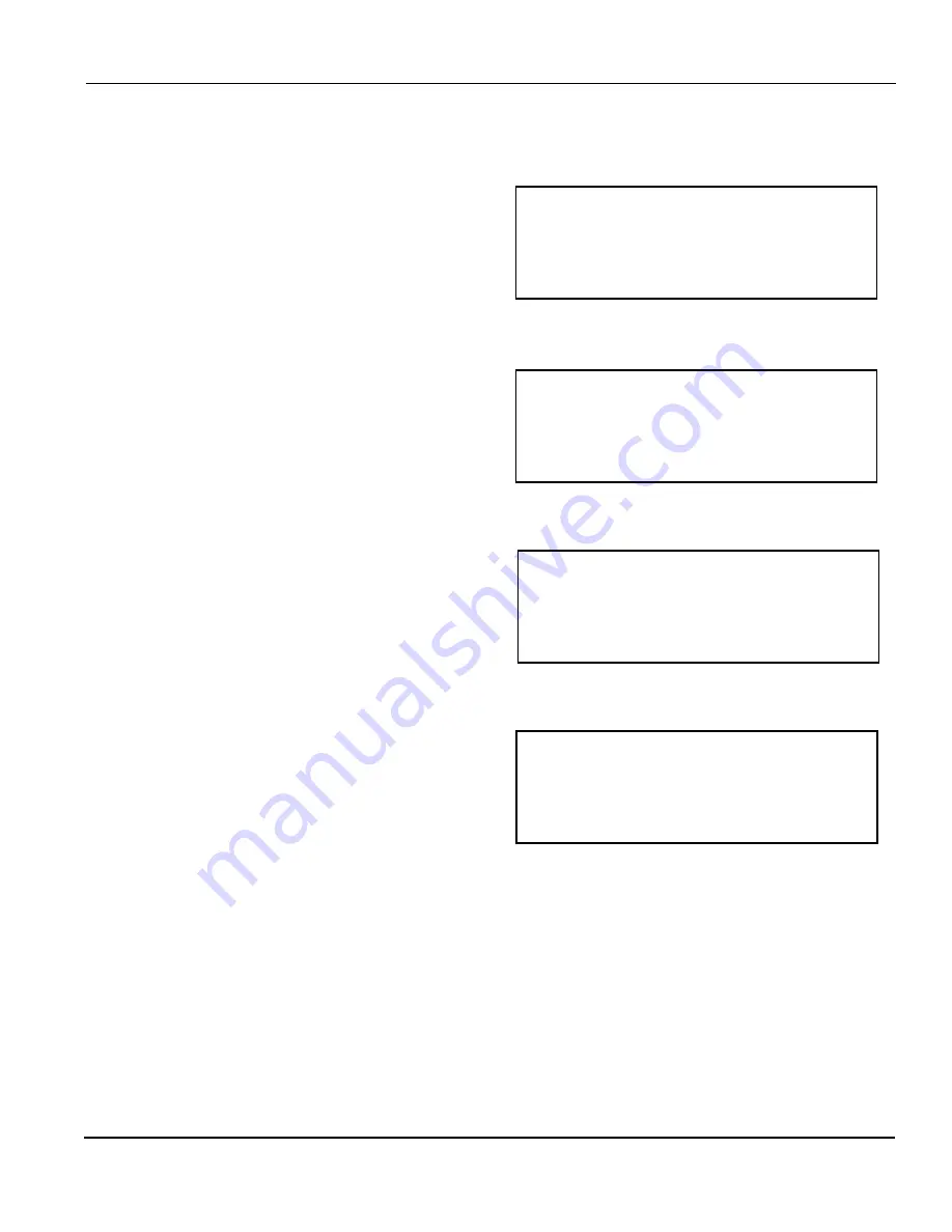
Figure 4.16
First Programmable Parameters Screen
>>Logic
Stop Type
Message
Open Angle
Figure 4.17
Second Programmable Parameters Screen
Close Angle
Figure 4.15
Second User Inputs Screen
Input #5
Input #6
>Input #7 (cyclic)
Input #8 (cyclic)
Figure 4.18
Example of a Programming Screen
PROGRAMMING:
Input #1 Logic
OFF


