OPERATION AND INSTALLATION
RCI-4100 SYSTEM
MAN-1111 Rev H
©Copyright 2015 LSI-Robway Pty Ltd
Page 22
2.3.10.
Cable Glands
The cable glands used on the flameproof Control Unit are barrier glands. Instructions to fit cables and
epoxy compound are included with each gland. Once the epoxy has been installed, the gland must
not be re-opened as the seal will be broken. If any cable alterations are necessary, then a new barrier
gland must be used. The particular glands recommended utilise a unique clamp arrangement which
allows either steel wire armour or steel braid armour to be clamped within the gland. It is important to
follow the instructions carefully to use the correct orientation of the clamp to suit the particular cable,
and that either the armour (for power and relay cables) or the screen (I.S. cables) is clamped
correctly. Do not bring the screen connection through the gland (on I.S. cables) unless the
replacement gland is not suitable. In this case the screens must be terminated at the earth terminal
block located above the relays on the mounting plate inside the Control Unit.
CAUTION: DO NOT BRING THE SCREEN CONNECTION THROUGH THE GLAND (ON
I.S. CABLES). ONLY “SCREEN CAPTURE” GLANDS SHOULD BE USED.
Refer to APPENDIX G, Cable Gland Installation Instructions.
2.3.11.
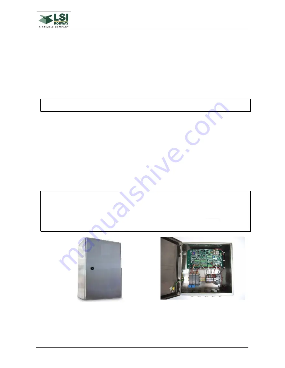
Safe Area Control Unit (if not hazardous area)
The Safe Area Control Unit enclosure is made of stainless steel with a hinged lid and is designed for
mounting inside the crane cabin.
The enclosure has overall outside dimensions of 275mm (H) x 350mm (W) x 200mm (D) with an
environmental protection of IP65.
The Control Unit contains the termination points for all modules within the RCI-4100 system.
Terminate all connection cables at the Control Unit.
Reference the applicable drawing(s) in APPENDIX N, System Drawings
CAUTION: CHECK ELECTRICAL CONNECTION BETWEEN THE CONTROL UNIT
ENCLOSURE AND THE GROUNDED CRANE CHASSIS. IF A GOOD
CONNECTION CANNOT BE ENSURED THROUGH THE MOUNTING
BRACKET, THEN INSTALL AN EARTH STRAP. IT IS A CONDITION OF
INSTALLATION THAT AN EQUIPOTENTIAL CONNECTION MUST BE
ENSURED BETWEEN THE DISPLAY ENCLOSURE AND THE CONTROL UNIT
ENCLOSURE (VIA THE GROUNDED CRANE CHASSIS).
Figure 6 - Typical safe area control unit inside the operator’s cabin
Summary of Contents for RCI-4100
Page 2: ......
Page 6: ......
Page 8: ......
Page 28: ......
Page 36: ......
Page 58: ......
Page 70: ......
Page 82: ......
Page 88: ......
Page 92: ......
Page 94: ......
Page 100: ......
Page 102: ......
Page 104: ......
Page 106: ......
Page 108: ......
Page 110: ......
Page 112: ......
Page 114: ......
Page 126: ......
Page 128: ......
Page 130: ......
Page 132: ......
Page 140: ......
Page 142: ...WIND SPEED MONITORING OPTION MAN 1111 Rev H Copyright 2015 LSI Robway Pty Ltd Page 142 ...
Page 144: ......
Page 147: ...WIND DIRECTION MONITORING MAN 1111 Rev H Copyright 2015 LSI Robway Pty Ltd Page 147 ...
Page 148: ......
Page 150: ......
Page 156: ......
Page 158: ......
Page 162: ...TILT SENSING OPTION MAN 1111 Rev H Copyright 2015 LSI Robway Pty Ltd Page 162 ...
Page 164: ......
Page 170: ......
Page 171: ...SYSTEM DRAWINGS MAN 1111 Rev H Copyright 2015 LSI Robway Pty Ltd Page 171 ...
Page 172: ...SYSTEM DRAWINGS MAN 1111 Rev H Copyright 2015 LSI Robway Pty Ltd Page 172 ...
Page 173: ...SYSTEM DRAWINGS MAN 1111 Rev H Copyright 2015 LSI Robway Pty Ltd Page 173 ...
Page 174: ...SYSTEM DRAWINGS MAN 1111 Rev H Copyright 2015 LSI Robway Pty Ltd Page 174 ...
Page 175: ...SYSTEM DRAWINGS MAN 1111 Rev H Copyright 2015 LSI Robway Pty Ltd Page 175 ...
Page 176: ...SYSTEM DRAWINGS MAN 1111 Rev H Copyright 2015 LSI Robway Pty Ltd Page 176 ...
Page 177: ...SYSTEM DRAWINGS MAN 1111 Rev H Copyright 2015 LSI Robway Pty Ltd Page 177 ...
Page 178: ...SYSTEM DRAWINGS MAN 1111 Rev H Copyright 2015 LSI Robway Pty Ltd Page 178 ...
Page 179: ...SYSTEM DRAWINGS MAN 1111 Rev H Copyright 2015 LSI Robway Pty Ltd Page 179 ...
Page 180: ......
Page 182: ......


