


OPERATION AND INSTALLATION
RCI-4100 SYSTEM
MAN-1111 Rev H
©Copyright 2015 LSI-Robway Pty Ltd
Page 21
WARNING: THE MACHINED SURFACES BETWEEN THE CONTROLLER BODY AND LID
ARE A CRITICAL DESIGN PROTECTION MEASURE. DAMAGE TO THESE
SURFACES CAN ADVERSELY AFFECT THE EX D PROTECTION
MEASURES AND THE ENCLOSURE MUST BE REPLACED IF THERE IS ANY
PITTING OR SCORING PRESENT.
The Control Unit contains the termination points for all modules within the RCI-4100IS system.
Terminate all connection cables in the Control Unit.
Refer also Section 2.3.12 Cabling Instructions
Reference the applicable drawing(s) in APPENDIX N, System Drawings
CAUTION: CHECK ELECTRICAL CONNECTION BETWEEN THE CONTROL UNIT
ENCLOSURE AND THE GROUNDED CRANE CHASSIS. IF A GOOD
CONNECTION CANNOT BE ENSURED THROUGH THE MOUNTING
BRACKET, THEN INSTALL AN EARTH STRAP. IT IS A CONDITION OF
INSTALLATION THAT AN EQUIPOTENTIAL CONNECTION MUST BE
ENSURED BETWEEN THE DISPLAY ENCLOSURE AND THE CONTROL UNIT
ENCLOSURE (VIA THE GROUNDED CRANE CHASSIS).
Figure 6
-
Typical installation of Ex d control unit inside the operator’s cabin
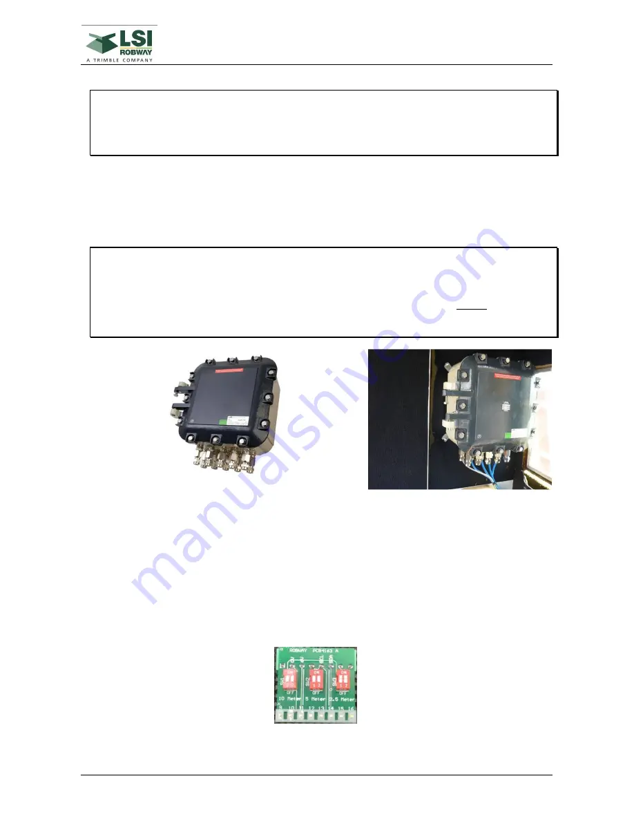
2.3.9.
Setting DIP Switches for Cable Length
The hazardous area control unit has a display barrier (BAREX4120) which the display is connected to.
This has a PCB with three DIP switches to match various display cable lengths to the display barrier.
After trimming the display cable to required length these DIP switches must be set as follows:
o
If the cable length is up to 2.5 metres in length then the 2.5 meter switch (SW3) is set to “ON”
and switches SW1 and SW2 are set to “OFF”.
o
If the cable length is greater than 2.5 metres up to 5 metres in length then the 5 meter switch
(SW2) is set to “ON” and switches SW1 and SW3 are set to “OFF”.
o
If the cable length is greater than 5 metres up to 10 metres in length then the 10 meter switch
(SW1) is set to “ON” and switches SW2 and SW3 are set to “OFF”.
Figure 7 - DIP Switches for Cable Length - CIRPCB4163
Summary of Contents for RCI-4100
Page 2: ......
Page 6: ......
Page 8: ......
Page 28: ......
Page 36: ......
Page 58: ......
Page 70: ......
Page 82: ......
Page 88: ......
Page 92: ......
Page 94: ......
Page 100: ......
Page 102: ......
Page 104: ......
Page 106: ......
Page 108: ......
Page 110: ......
Page 112: ......
Page 114: ......
Page 126: ......
Page 128: ......
Page 130: ......
Page 132: ......
Page 140: ......
Page 142: ...WIND SPEED MONITORING OPTION MAN 1111 Rev H Copyright 2015 LSI Robway Pty Ltd Page 142 ...
Page 144: ......
Page 147: ...WIND DIRECTION MONITORING MAN 1111 Rev H Copyright 2015 LSI Robway Pty Ltd Page 147 ...
Page 148: ......
Page 150: ......
Page 156: ......
Page 158: ......
Page 162: ...TILT SENSING OPTION MAN 1111 Rev H Copyright 2015 LSI Robway Pty Ltd Page 162 ...
Page 164: ......
Page 170: ......
Page 171: ...SYSTEM DRAWINGS MAN 1111 Rev H Copyright 2015 LSI Robway Pty Ltd Page 171 ...
Page 172: ...SYSTEM DRAWINGS MAN 1111 Rev H Copyright 2015 LSI Robway Pty Ltd Page 172 ...
Page 173: ...SYSTEM DRAWINGS MAN 1111 Rev H Copyright 2015 LSI Robway Pty Ltd Page 173 ...
Page 174: ...SYSTEM DRAWINGS MAN 1111 Rev H Copyright 2015 LSI Robway Pty Ltd Page 174 ...
Page 175: ...SYSTEM DRAWINGS MAN 1111 Rev H Copyright 2015 LSI Robway Pty Ltd Page 175 ...
Page 176: ...SYSTEM DRAWINGS MAN 1111 Rev H Copyright 2015 LSI Robway Pty Ltd Page 176 ...
Page 177: ...SYSTEM DRAWINGS MAN 1111 Rev H Copyright 2015 LSI Robway Pty Ltd Page 177 ...
Page 178: ...SYSTEM DRAWINGS MAN 1111 Rev H Copyright 2015 LSI Robway Pty Ltd Page 178 ...
Page 179: ...SYSTEM DRAWINGS MAN 1111 Rev H Copyright 2015 LSI Robway Pty Ltd Page 179 ...
Page 180: ......
Page 182: ......